Induction heat treatment method and article treated thereby

a carburizing process and induction heat treatment technology, applied in heat treatment apparatus, couplings, furnaces, etc., can solve the problems of unsatisfactory results, unsatisfactory results, and inability to achieve the effect of improving the metallurgical and mechanical properties of components, improving the production of such components, and improving the quality of finished parts

Inactive Publication Date: 2005-02-24
AUTOMOTIVE COMPONENTS HOLDINGS
View PDF23 Cites 10 Cited by
  • Summary
  • Abstract
  • Description
  • Claims
  • Application Information

AI Technical Summary

Benefits of technology

[0011] The present invention undertakes to improve the production of such components as compared to previous methods, such as carburizing, by enabling the use induction hardening, and thereby providing better control over the hardening process by hardening one component at a time, improving the metallurgical and mechanical and properties of the components, and allowing for a reduction in heat treatment cost.
[0012] The hardening operation will be simplified, and allow improved control, by the application of this invention because the components will be processed one at a time. The integration of the part location, heating, and quenching functions into a single, robust machine simplifies the heat treatment operation compared to previous methods, such as carburizing, by reducing the part handling requirements and reducing complex cycle parameters (e.g. adjusting the entire process for part-to-part variations in a batch of parts due to different temperature and environmental conditions that exist in a large heat treating furna...

Problems solved by technology

The use of carburizing for case hardening has a number of well-known limitations.
These include the fact that the process treats the entire surface of the component, the material and processing costs associated with the process, the processing time necessary to heat the parts to temperature and produce the required carburized case depth, as well as limitations related to process control, batch processing, capital expense and facility requirements for large furnaces, environmental issues, and control of the finished part quality.
Also, the carburizing process has the potential to form undesirable microstructures, which include carbides, grain boundary oxidation, decarburization and retained austenite that can each affect the functionality of the finished part.
However, induction hardening has significant limitations in cases where the surface requiring heat treatment is irregular, s...

Method used


Image

  • Induction heat treatment method and article treated thereby
  • Induction heat treatment method and article treated thereby
  • Induction heat treatment method and article treated thereby

Examples


Embodiment Construction

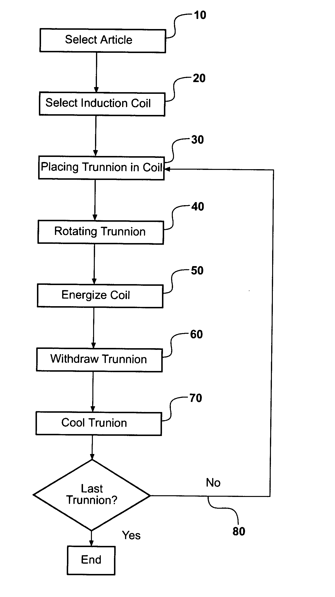
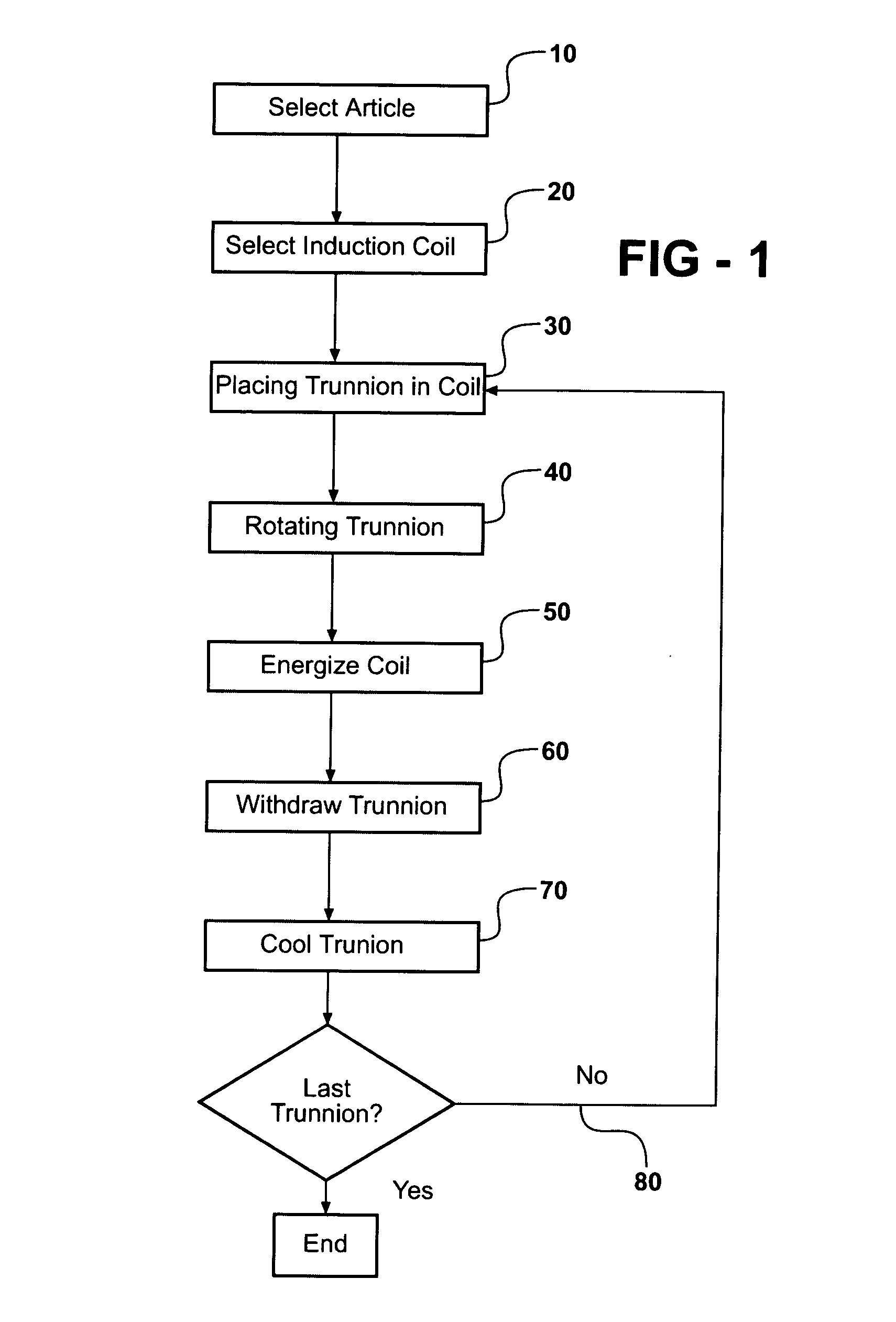
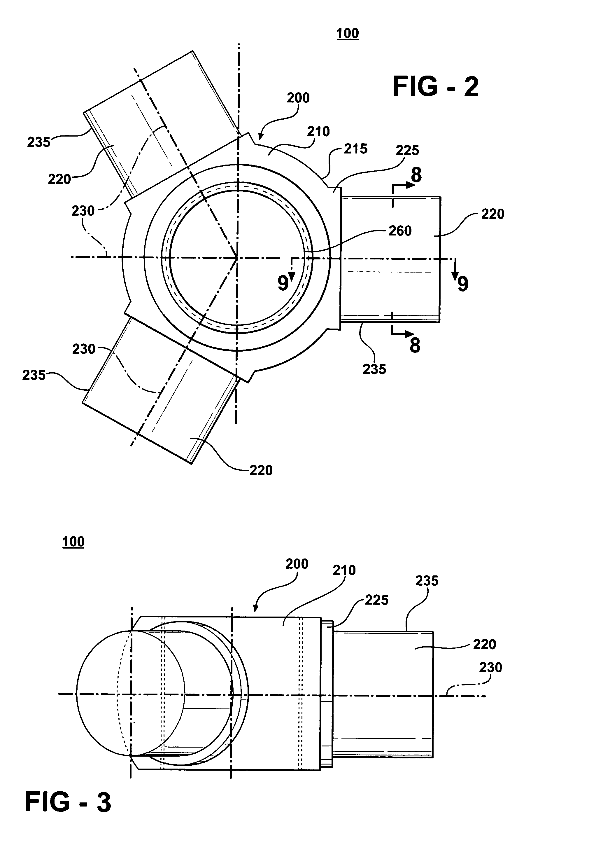
[0031] Referring to FIGS. 1-7, the present invention generally comprises a method 1 of induction heat treatment, comprising the steps of: (1) selecting 10 an article 100, such as spider 200, for heat treatment comprising hub 210 having hub surface 215 and a plurality of angularly spaced trunnions 220 extending from a corresponding plurality of trunnion shoulders 225 formed in the hub surface 215, each trunnion shoulder 225 having a trunnion shoulder surface 245, and each trunnion 220 having a trunnion axis 230 and a trunnion surface 235; (2) selecting 20 an induction coil 300, which is adapted to receive a trunnion 220 for heat treatment and apply a magnetic field to the trunnion surface 235 and trunnion shoulder surface 245; (3) placing 30 a trunnion 220 within the induction coil 300 with its corresponding trunnion shoulder 225 adjacent to the induction coil 300; (4) rotating 40 the trunnion 220 within the induction coil 300 about the trunnion axis 230 at a selected speed; (5) ener...


PUM

PropertyMeasurementUnit
Temperatureaaaaaaaaaa
Depthaaaaaaaaaa
Temperatureaaaaaaaaaa

Abstract

A method of induction heat-treating certain surfaces of an article comprising a hub and a plurality of trunnions or shafts extending therefrom, wherein the surfaces to be heat-treated comprise the surfaces of the trunnions. The method employs an induction coil that provides a planar magnetic field that is adapted to the irregular shape of the article, such that the induction coil produces magnetic fields that are adapted to induce currents in, and thereby heat, the trunnion surfaces of the article. The method and induction coil are particularly adapted to provide an induction hardening heat treatment for trunnion surfaces of trunnions used in steel spiders of spider or tripod-type constant velocity joints.

Description

FIELD OF THE INVENTION [0001] The present invention relates to a method of induction heat treatment. More specifically, the invention comprises a method for induction hardening certain metal components, particularly those having a shape that prevents uniform induction coupling over the entire surface to be hardened in a single step. Most particularly, the invention comprises a method for induction hardening the outer surfaces of the trunnions of a spider of a steel tripod-type constant velocity joint. BACKGROUND OF THE INVENTION [0002] The tripod-type constant velocity joint is widely used in automotive vehicles. It is most frequently used to provide a plunging and angulating constant velocity joint for use with halfshafts, the name given to the two driveshafts or axle shafts that run from the transaxle to the wheels in front wheel drive vehicles. A plunging joint is one that permits axial movement between the shafts. Because it is widely used in automotive vehicles, the tripod join...

Claims


Application Information

Patent Timeline
IPC IPC(8): C21D1/10C21D9/00C21D9/28
CPCC21D1/10C21D9/28C21D9/0068Y02P10/25F16D3/2055F16D2250/0053
Inventor CHRISTOFIS, MARKHOPSON, MICHAEL WALTERSZCZOMAK, TEDSZALONY, NORMANSAMS, ROBERT W.SEIDEL, RICHARD LAWRENCEBOGEN, WILLIAM PAUL
Owner AUTOMOTIVE COMPONENTS HOLDINGS
Why Eureka
Try Eureka