Electrostatic coalescer device and use of the device

a coalescer and electrostatic technology, applied in the direction of electrolysis components, hydrocarbon oil refining, solid separation, etc., can solve the problems of both bare electrodes and coalescer with bare electrodes in contact with fluids that cannot withstand the condition of being flooded with water, rendering the electrical system inoperative, etc., to reduce the overall size of the separator vessel and reduce the number of vessels

Inactive Publication Date: 2005-02-24
SULZER MANAGEMENT AG
View PDF8 Cites 27 Cited by
  • Summary
  • Abstract
  • Description
  • Claims
  • Application Information

AI Technical Summary

Benefits of technology

[0011] Another object of the invention is to provide a device that contributes to a reduction of the overal

Problems solved by technology

A drawback of the separators disclosed in U.S. Pat. Nos. 4,469,582 and 4,919,777 is that they both use bare electrodes.
A coalescer with bare electrodes in contact with the fluids would not withstand the condition of being flooded with water.
The saline water is conductive and will s

Method used


Image

  • Electrostatic coalescer device and use of the device
  • Electrostatic coalescer device and use of the device
  • Electrostatic coalescer device and use of the device

Examples


Embodiment Construction

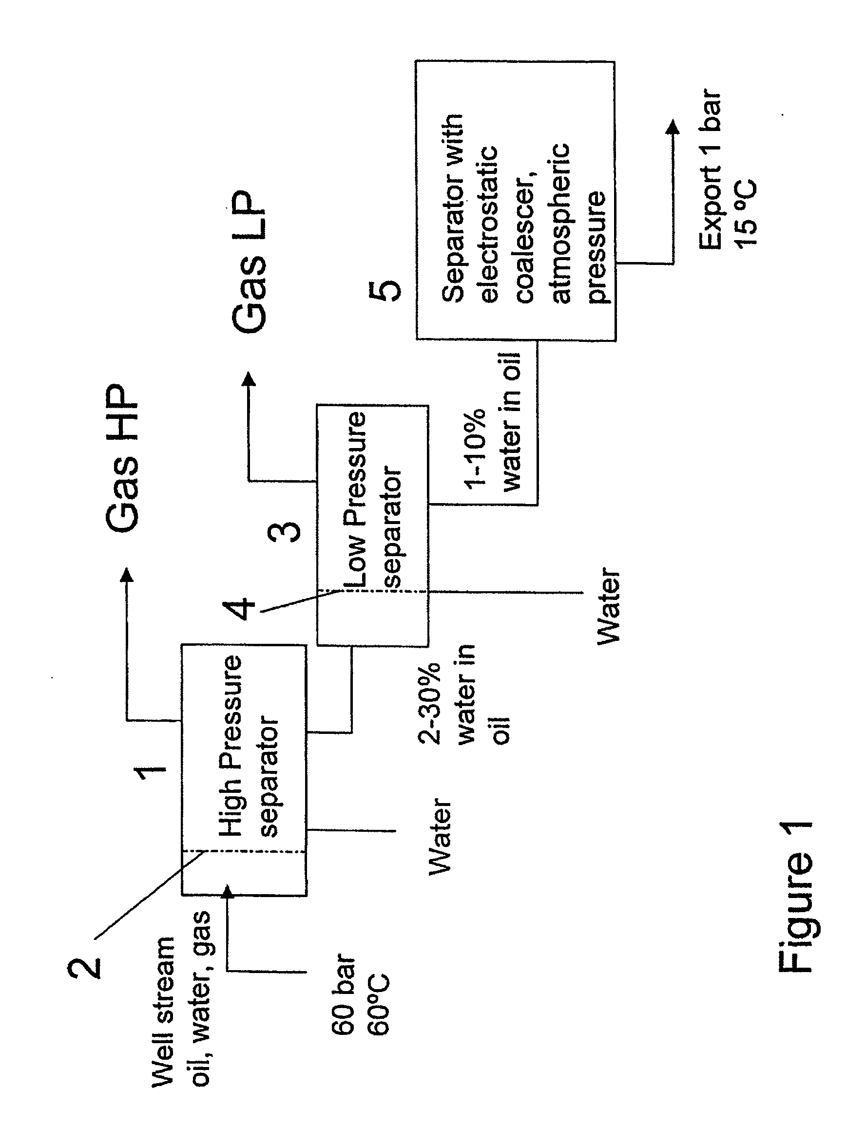
[0026]FIG. 1 is a schematic drawing of a separator system, normally placed downstream the wellhead. Some of the requirements for such a separator system are to bring down the pressure and temperature of the oil production stream from the well (typically 60 bar and 60° C., respectively) to typically 1 bar and 15° C. for export. In addition, the exported oil should contain less than 0.5% water. To meet these requirements, a three-stage process can be used, comprising three gravity separator tanks 1, 3, 5. A well stream containing oil, water and gas is entering the first separator 1. The separator 1 has a flow straightener 2 at the inlet. The flow straightener acts to ensure proper plug-flow in the main body of the tank, i.e. to distribute and homogenise the multi-phase flow over the cross section of the tank. The flow straightener is normally a perforated plate with a certain pressure loss to evenly distribute the volume flow. Typically, the perforation is 15-25% of the cross sectiona...


PUM

PropertyMeasurementUnit
Diameteraaaaaaaaaa
Diameteraaaaaaaaaa
Electric energyaaaaaaaaaa

Abstract

A device, located in a separator vessel having an inlet and a number of outlets, through which a mixture of fluids flows, for promoting electrostatic coalescence of a first conductive fluid emulsified in a second fluid, said device comprises a number of tubular electrostatic coalescer elements extending in the flow direction which are arranged in a matrix substantially covering the entire cross sectional area of said vessel, and means to apply an electrical field to the fluids flowing through said coalescer elements.

Description

TECHNICAL FIELD [0001] The present invention relates to an electrically energised device for use in the separation of a first conductive fluid, emulsified in a second fluid. The invention finds its main application in the oil industry. It is particularly advantageous in off-shore applications in which equipment is arranged for the purpose of promoting or effectuating a pre-separation of water from oil, or a water droplet enlargement, before an extracted emulsion comprising oil and water is further conducted to a subsequent settling tank for gravitational settling. BACKGROUND OF THE INVENTION [0002] Fluids produced from an underground formation, is usually a three-phase mixture of water, oil and gas, in which at least some of the water is emulsified in the oil. This mixture of fluids is usually separated into its phases downstream of the wellhead, in order to be deliverable to pipelines for further distribution. A possible method for performing such a separation is to use a three-sta...

Claims


Application Information

Patent Timeline
IPC IPC(8): B01D17/04
CPCB01D17/045B01D17/06
Inventor NILSEN, PAL JAHRESANDE, GORMPIASECKI, WOJCIECH
Owner SULZER MANAGEMENT AG
Why Eureka
Try Eureka