Semiconductor integrated circuit

Inactive Publication Date: 2005-02-24
SHARP KK
View PDF8 Cites 15 Cited by
  • Summary
  • Abstract
  • Description
  • Claims
  • Application Information

AI Technical Summary

Benefits of technology

[0035] According to an IC card of the present invention, a semiconductor integrated circuit to be mounted demonstrates an effect by the semiconductor integrated circuit

Problems solved by technology

Moreover, there is a problem that electromagnetic noises are radiated to the outside of a semiconductor integrated circuit to cause another semiconductor integrated circuit to malfunction depending on the amplitude of a clock signal or the like in the semiconductor integrated circuit and a hazard that the semiconductor integrated circuit malfunctions due to electromagnetic noises from another unit.
However, as described above, by forming the shielding film 1 on almost the entire surface of the semiconductor chip, a problem occurs that a stress caused by a difference between thermal expansion coefficients of the shielding film 1 and an interlayer insulating film 7 or a difference between thermal expansion coefficients of the shielding film 1 and a semiconductor substrate 4 increases and a shift between the shielding film 1

Method used


Image

  • Semiconductor integrated circuit
  • Semiconductor integrated circuit
  • Semiconductor integrated circuit

Examples


first embodiment

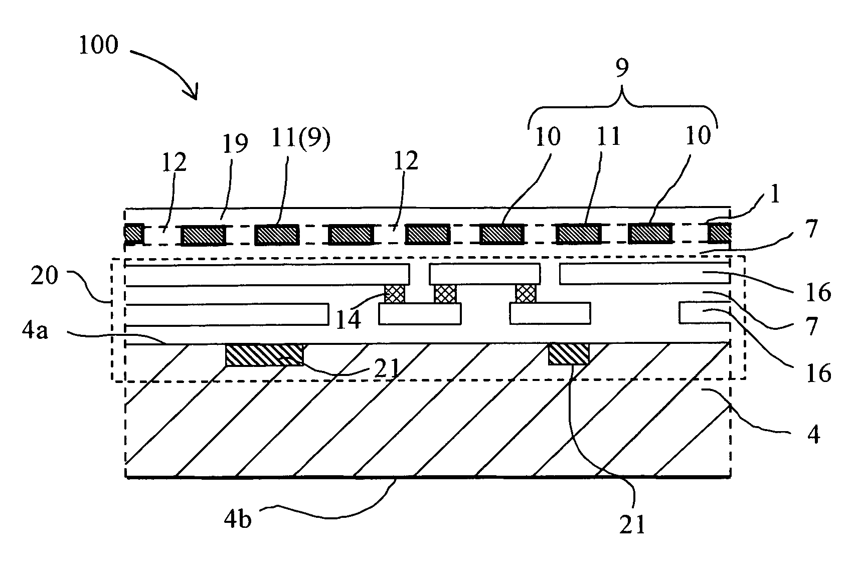
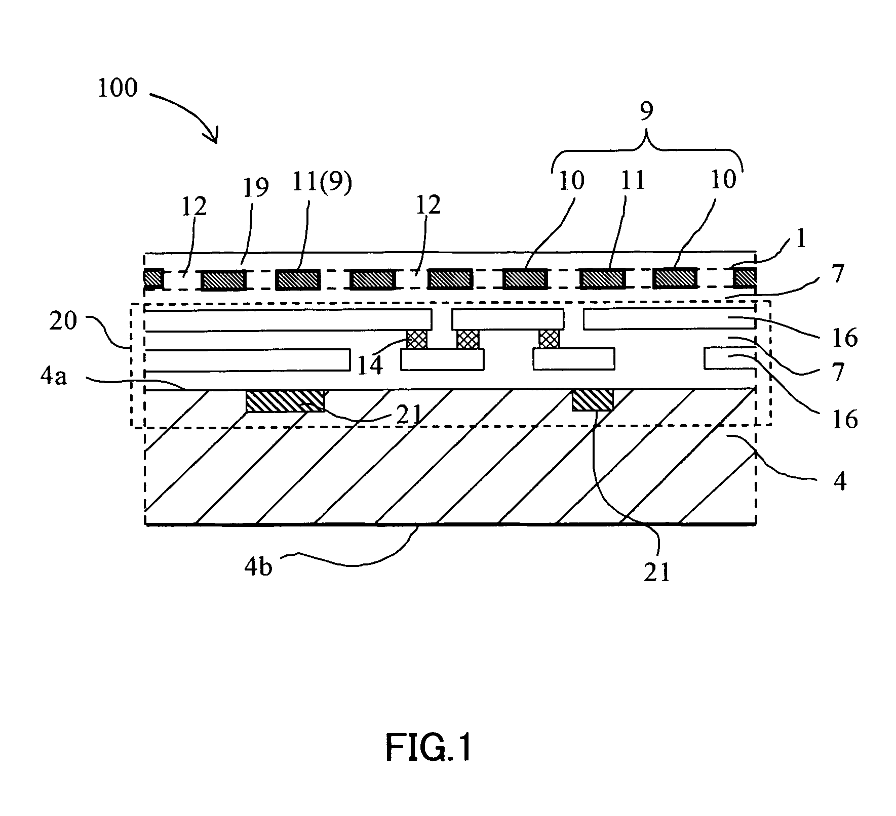
[0057]FIG. 1 schematically shows a sectional structure of a present invention circuit 100 of the As shown in FIG. 1, the present invention circuit 100 is formed by a circuit device 21 constituted by a MOSFET, diode, and resistance on the surface 4a of a semiconductor substrate 4 such as a single-crystalline silicon substrate by the normal semiconductor fabrication process and moreover forming a signal wiring between circuit devices 21 and a signal line for inputting / outputting a signal from or to the outside of the present invention circuit 100 by a metallic wiring 16. The metallic wiring 16 is formed on the upper portion than the circuit device 21 on the surface 4a of the semiconductor substrate 4 and moreover, the shielding film 1 according to the same metallic layer as the metallic wiring 16 is formed on the upper layer of a circuit structural portion 20 formed by the circuit device portion 21 and metallic wiring 16. The shielding film 1 has a shielding portion 9 and an opening ...

second embodiment

[0064] (Second Embodiment)

[0065]FIG. 5 shows a pattern (portion) and a top viewed structure of the shielding film 1 of the present invention circuit 100 of the second embodiment. The sectional structure of the present invention circuit 100 is the same as the first embodiment. The difference from the first embodiment is the pattern shape of the shielding film 1. In the case of the shielding film pattern of the first embodiment, the opening 12 and independent shielding portion 11 are formed in one large continuous shielding portion 10. In the case of the second embodiment, however, the continuous shielding portion 10 is divided into two continuous shielding portions 10a and 10b by an isolating space 35. Thus, when a plurality of continuous shielding portions 10 are present by being electrically isolated, it is possible to use the continuous shielding portions 10a and 10b as power supply wirings having potential levels different from each other. In this case, by connecting the continuo...

third embodiment

[0068] (Third Embodiment)

[0069]FIG. 10 schematically shows a sectional structure of a present invention circuit 101 of third embodiment. The present invention circuit 101 is different from the present invention circuit 100 in that shielding films 1 are constituted by two layers and have a upper shielding film 1a and a lower shielding film 1b. How to form a circuit device portion 21, signal wiring, shielding films 1a and 1b, and interlayer insulating film 7 and a material used and film thickness are the same as the case of the first embodiment. However, the lower shielding film 1b has the same thickness as the metallic wiring 16.

[0070] In the case of the third embodiment, it is possible to completely shield a circuit structure portion 20 by using two layers of the shielding film 1 of the upper shielding film 1a and the lower shielding film 1b and prevent the circuit structure portion 20 from optical observation by an optical microscope or observation by an electronic beam tester. Ea...


PUM


Abstract

In a semiconductor integrated circuit (100) having a shielding film (1) formed by a material different from at least either of a semiconductor substrate (4) and an interlayer insulating film (7) in thermal expansion coefficient, the shielding film (1) has shielding portions (9) and openings (12), and at least either of a plurality of independent openings (12a) whose circumferences are surrounded by the shielding portions (9) and a plurality of independent shielding portions (11) whose circumferences are surrounded by the openings (12) is present and scattered on the entire surface of a chip. Or, a plurality of openings (12) are present on an optional straight line parallel with the surface (4a) of the semiconductor substrate (4) passing through a portion for shielding circuit devices (21) and circuit wirings (16) in the shielding portions (9).

Description

BACKGROUND OF THE INVENTION [0001] 1. Field of the Invention [0002] The present invention relates to a semiconductor integrated circuit, particularly to an art effectively applied to a semiconductor integrated circuit having a multilayer wiring structure. [0003] 2. Description of the Related Art [0004] In the case of a semiconductor integrated circuit, a product is born which has a multilayer wiring structure constituted by forming a large-scale circuit device group on the surface of a semiconductor substrate and alternately heaping an insulating layer and a wiring layer to be electrically connected. Some of the semiconductor integrated circuits have a memory in which important confidential information is included or a circuit including an advanced intellectual property. Therefore, it may be preferable to take action so that information is not altered or analyzed. [0005] Moreover, there is a problem that electromagnetic noises are radiated to the outside of a semiconductor integrate...

Claims


Application Information

Patent Timeline
IPC IPC(8): G06K19/077H01L21/3205H01L21/822H01L23/52H01L23/522H01L23/552H01L23/58H01L27/04
CPCH01L23/5225H01L23/552H01L2924/13091H01L2224/16145H01L23/57H01L21/3205
Inventor HENMI, TAKUYA
Owner SHARP KK
Why Eureka
Try Eureka