Laser system

a laser system and laser beam technology, applied in the field of laser beam systems, can solve the problems of inability to detect the actual intensity inability to perform high-quality auto power control, and difficulty in performing output control of the laser beam, so as to improve the degree of freedom in positioning and high accuracy. , the effect of high accuracy

Inactive Publication Date: 2005-02-24
KK TOPCON
View PDF2 Cites 14 Cited by
  • Summary
  • Abstract
  • Description
  • Claims
  • Application Information

AI Technical Summary

Benefits of technology

[0026] The present invention provides a laser system for controlling output of a laser oscillator based on a monitor light obtained by splitting a laser beam, comprising a light emitting means for emitting the laser beam, a luminous flux splitting means disposed on an optical path of the laser beam and reflecting a part of the laser beam as a monitor light, and a photodetecting means for receiving the monitor light, wherein the luminous flux splitting means has a reflection surface of an incident angle so that reflectivity is kept at approximately constant level with respect to the laser beam regardless of condition of polarization of the incident laser beam. As a result, even when the condition of polarization of the projected laser beams is changed, the monitor light accurately reflects light intensity of the projection, and it is possible to perform output control with high accuracy.
[0027] Also, according to the present invention, when the reflection surface of the luminous flux splitting means is set to the incident angle with respect to the laser beam, reflectivity is not changed with respect to the wavelength. Thus, it is possible to perform auto power control for the projected laser beam in reliable manner and with high accuracy even for the light emitting means provided with the light emitting elements emitting two or more laser beams with different wavelengths.
[0028] According to the present invention, the light guiding optical means is a light guiding fiber. This contributes to the improvement of the degree of freedom in the positioning of the photodetector and also to compact design of the module.

Problems solved by technology

Thus, actual intensity of the laser beam cannot be detected.
For this reason, there has been such problem that it is not possible to perform auto power control with high accuracy.
It is difficult to perform output control of the laser oscillator 1 by obtaining the monitor light 6 from the luminous flux splitting means 3, and it is a problem that the accuracy is low.
Therefore, there has been no other way but to perform auto current control in conventional type.
When the light emitting means provided with two or more semiconductor lasers 11a to emit laser beams with different wavelengths (different colors) is used and when the anti-reflective film is formed on the reflection surface of the luminous flux splitting means 3 for the purpose of suppressing the loss of light at the luminous flux splitting means 3, it is difficult to form the anti-reflective film to two or more wavelengths, and this leads to higher cost.

Method used


Image

  • Laser system
  • Laser system
  • Laser system

Examples


first embodiment

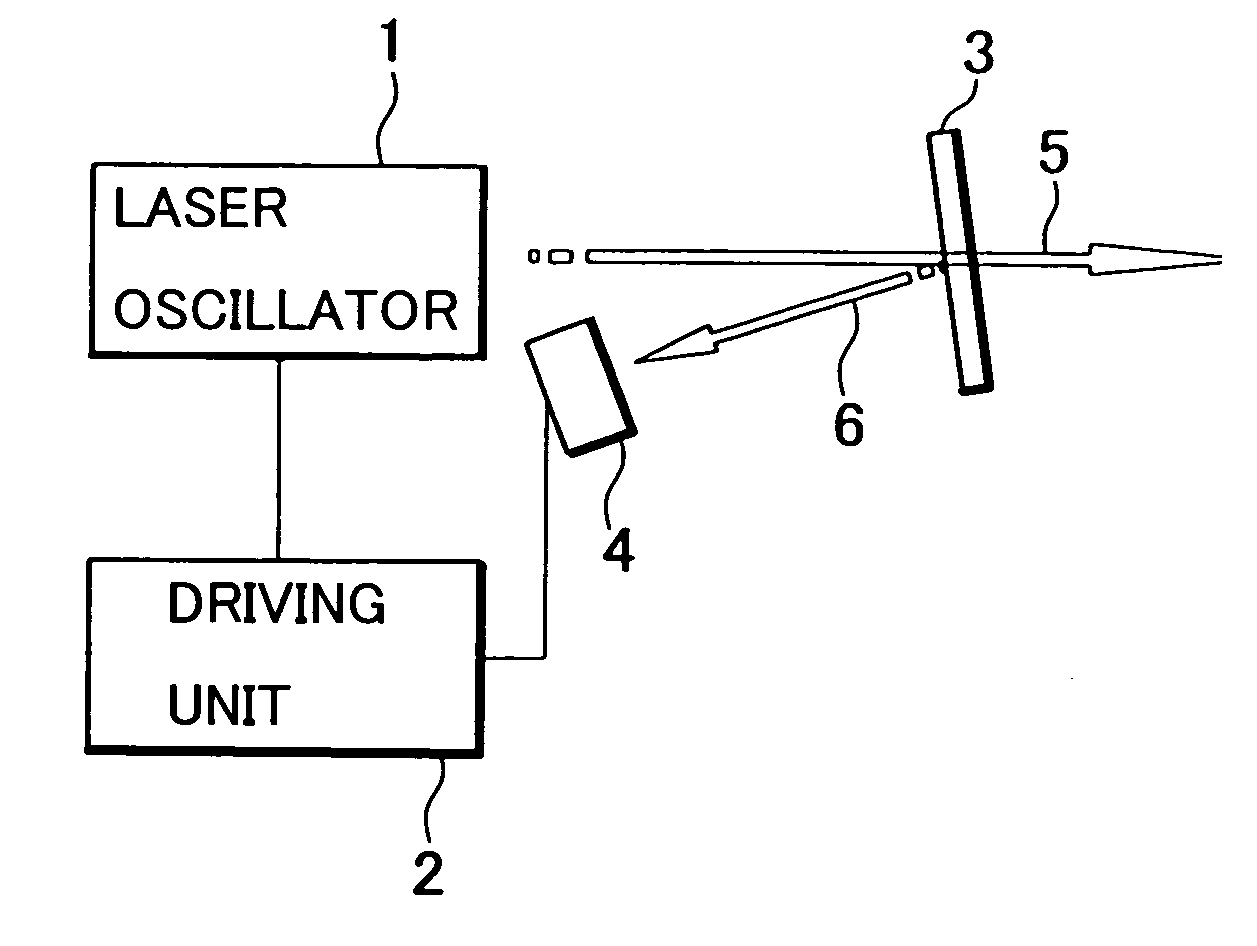
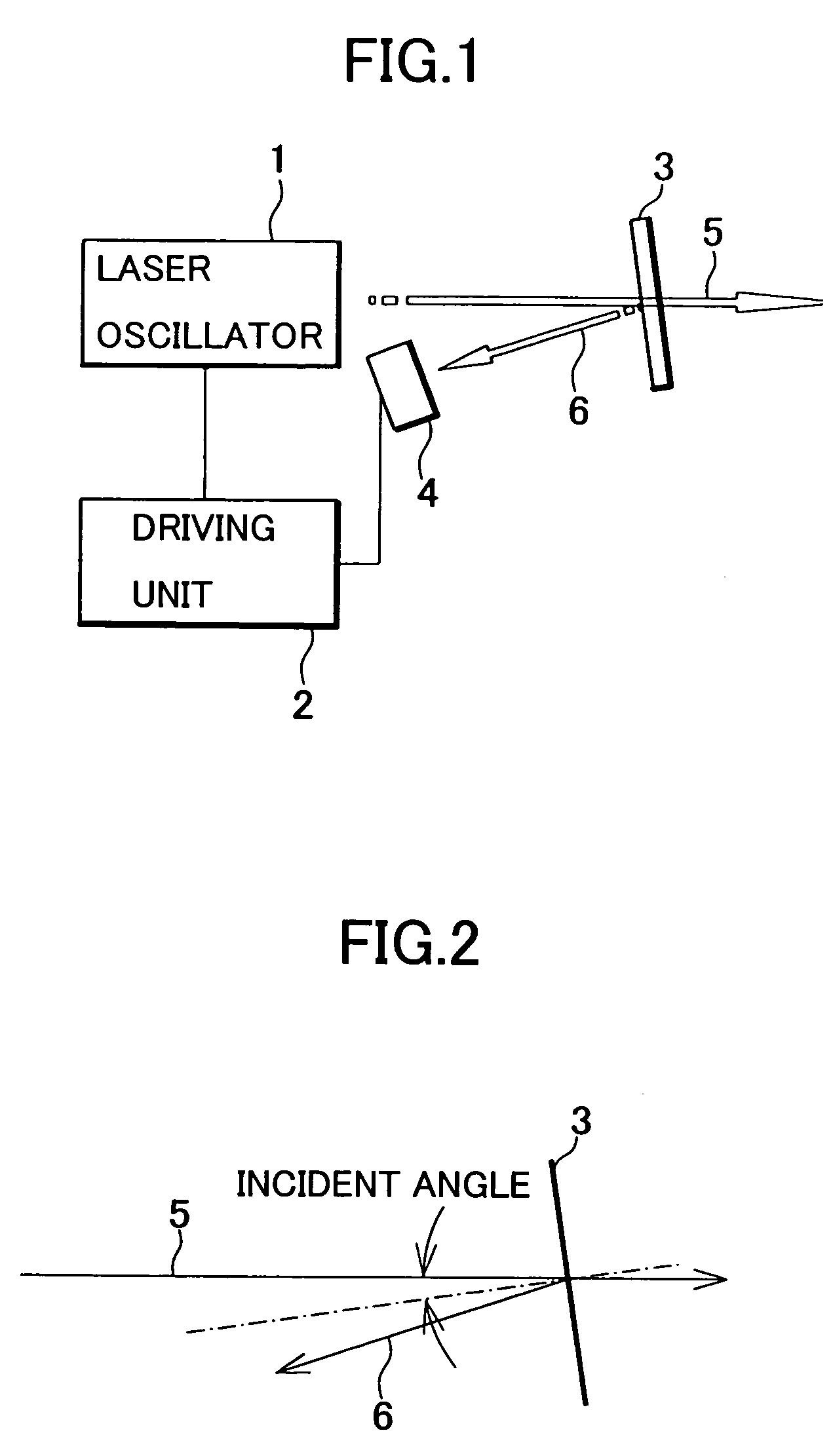
[0046] Description will be given on a first embodiment referring to FIG. 1 and FIG. 2.

[0047] In FIG. 1, the equivalent component as shown in FIG. 13 is referred by the same symbol.

[0048] On an optical path of a laser beam 5 emitted from a laser oscillator 1, a luminous flux splitting means 3 is provided. The luminous flux splitting means 3 is arranged in such manner that the laser beam 5 enters a reflection surface at an angle of less than about 10°. A photodetector (photodetection means) 4 for receiving a reflection light from the luminous flux splitting means 3 is oppositely positioned to the luminous flux splitting means 3.

[0049] As shown in FIG. 15, when a laser beam enters at an incident angle of less than about 10° with respect to a reflection surface, reflectivity is approximately on a constant level for both p-linear polarized light and s-linear polarized light. Further, the present inventors have also confirmed that reflectivity is approximately constant for both p-linear...

second embodiment

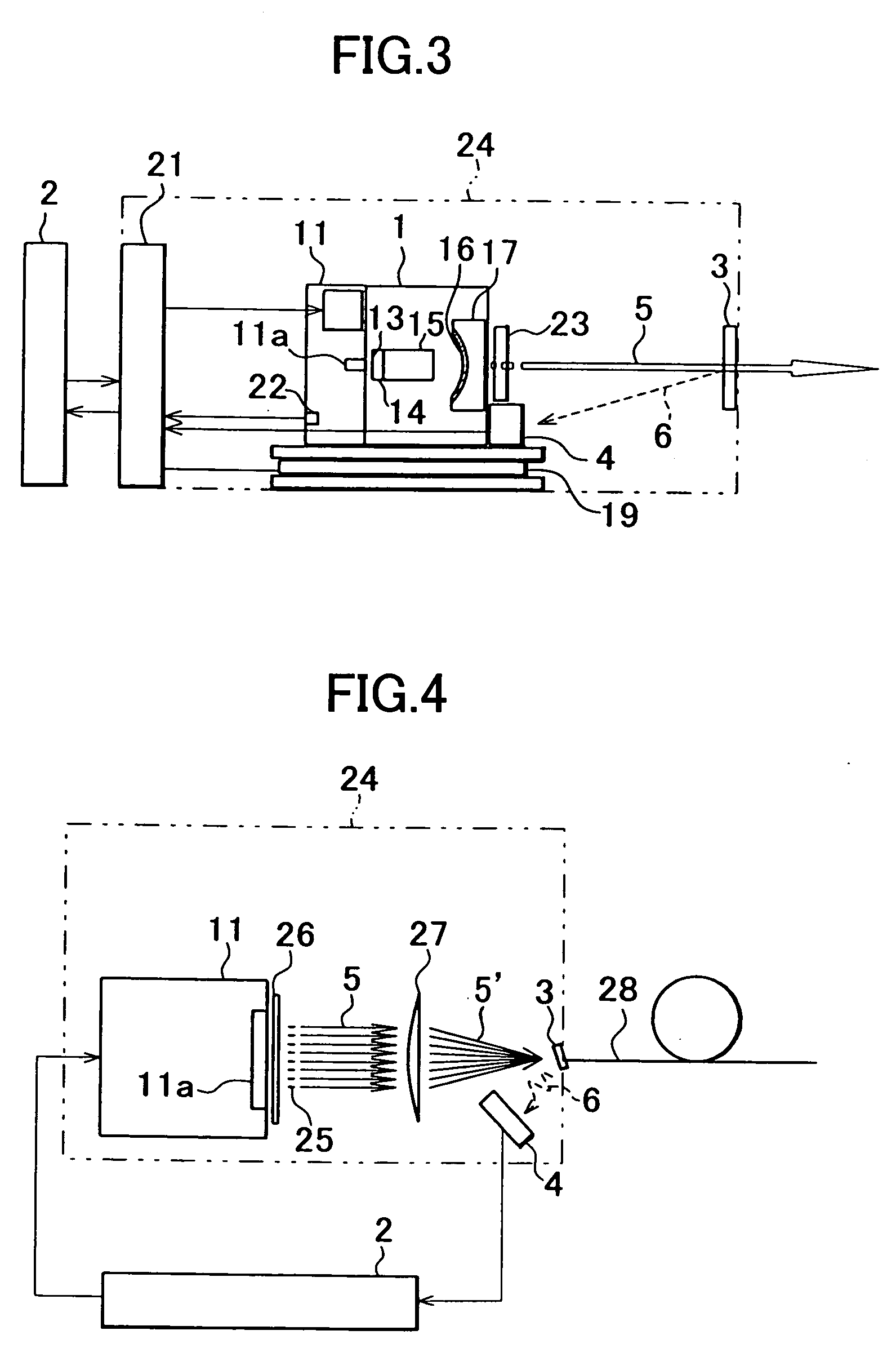
[0054]FIG. 3 shows a second embodiment, in which the present invention is applied to a diode pumped solid-state laser as shown in FIG. 14. In FIG. 3, the equivalent component as in FIG. 14 is referred by the same symbol.

[0055] The laser oscillator 1 shown in FIG. 3 is a diode pumped solid-state laser of intracavity type SHG mode for converting frequency of a laser beam from a semiconductor laser. An excitation light emitted from the LD light emitter 11 is converted to a fundamental light at the laser crystal 14. Further, the fundamental light is converted by wavelength conversion to a secondary higher harmonic wave at the non-linear optical medium 15.

[0056] The LD light emitter 11, the laser crystal 14, the non-linear optical medium 15, and the concave mirror 17, etc. are composed as an integrated the laser oscillator 1, and the laser oscillator 1 is placed on a chiller 19 such as a thermoelectric cooling element (TEC).

[0057] The driving unit 2 can drive and control the LD light e...

third embodiment

[0067] The third embodiment as shown in FIG. 4 can be applied to a case where relatively high laser beam intensity is required, e.g. in a medical system such as a laser operation system. In case two or more laser beams 5 are bundled together and are used, it is preferable to perform auto power control of overall output of the laser beams 5′ bundled together rather than to perform auto power control for each of the laser beams.

[0068] The monitor light 6 reflected by the luminous flux splitting means 3 is reflected at the same reflectivity to each of the laser beams 5 regardless of the condition of polarization and wavelength of each of the laser beams 5. Thus, the monitor light 6 generated as the result of the reflection of the laser beams 5′ by the luminous flux splitting means 3 accurately corresponds to overall output of the laser beam 5′.

[0069] Regardless of the condition of polarization and wavelength of each of the laser beams 5, auto power control with high accuracy can be ca...


PUM


Abstract

A laser system for controlling output of a laser oscillator based on a monitor light obtained by splitting a laser beam, comprising a light emitting means for emitting the laser beam, a luminous flux splitting means disposed on an optical path of the laser beam and reflecting a part of the laser beam as a monitor light, and a photodetecting means for receiving the monitor light, wherein the luminous flux splitting means has a reflection surface of an incident angle so that reflectivity is kept at approximately constant level with respect to the laser beam regardless of condition of polarization of the incident laser beam.

Description

BACKGROUND OF THE INVENTION [0001] The present invention relates to a laser system, and in particular, to a laser system for performing output control of laser. [0002] Referring to FIG. 13, description will be given below on a conventional type laser system for output control of laser. [0003] In FIG. 13, reference numeral 1 denotes a laser oscillator, 2 denotes a driving unit including a power source and a control unit, 3 represents a luminous flux splitting means, and 4 denotes a photodetector oppositely positioned to the luminous flux splitting means 3. [0004] The luminous flux splitting means 3 is arranged in an optical path of a laser beam 5 outputted from the laser oscillator 1 so that the luminous flux splitting means 3 has a reflection surface at an angle of 45° to the optical path. The luminous flux splitting means 3 reflects a part (e.g. 2%-5%) of the laser beam 5, and most of the laser beam 5 are allowed to pass. The photodetector 4 receives the reflection light 6 (hereina...

Claims


Application Information

Patent Timeline
Patent Type & Authority Applications(United States)
IPC IPC(8): H01S3/13H01S3/00H01S3/131
CPCH01S3/1312
Inventor MOMIUCHI, MASAYUKIENO, TAIZOGOTO, YOSHIAKI
Owner KK TOPCON
Why Eureka
Try Eureka