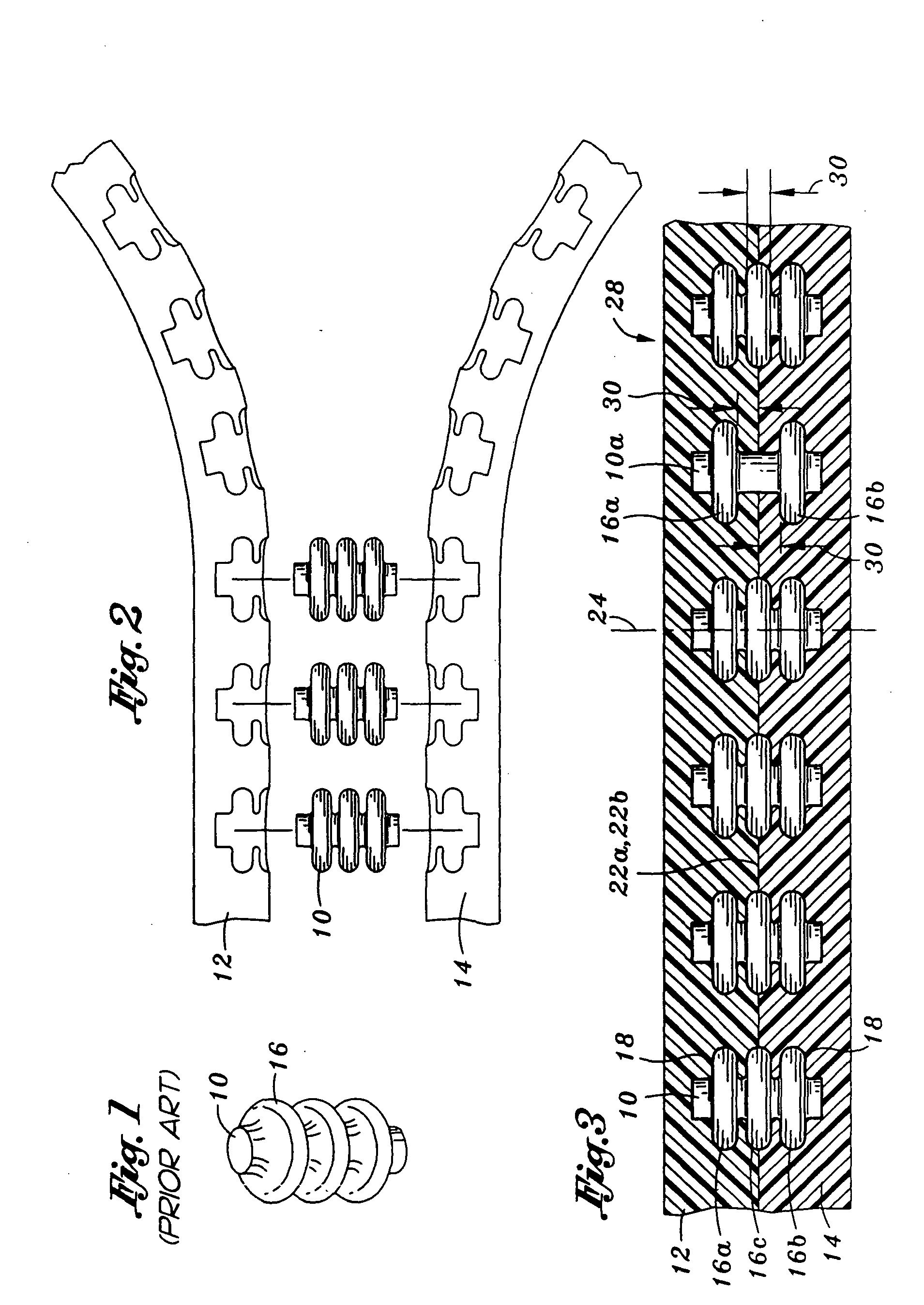
[0012] One unique aspect of the present invention is the capability to precisely position and orient the '593 Patent z-pins within the two layers. This capability overcomes deficiencies of the prior art as discussed in the background of the invention. For example, a '593 Patent z-pin having at least two radially extending
flange sections may have at least one
flange embedded in the first layers by physical consolidation processes,
casting, RTM, or other similar operation and at least one exposed
flange which is subsequently covered with uncured prepreg, speciality material, or lower temperature melting
metal alloy creating a single integral subassembly. The second or subsequent layers may be thermal or
acoustic insulation material,
molten metal, injection molded plastic, various other materials, or combinations thereof. The respective flange sections may be embedded within respective first and second layers to a depth equal to the width of the section or have the flanges embedded at the outer surface of either the first or second layer, or both. In this way, a pull out force of the '593 Patent z-pin in relation to the first and second layers may be increased to a level greater than the yield strength or ultimate strength of the '593 Patent z-pin itself. This capability to vary depth, flange width, and angular adjustment allows the pull out force to be greater than the
ultimate tensile strength of the base '593 Patent z-pin
diameter, thereby allowing the failure mode to be in the z-pin at that location. Conversely, design considerations may dictate the desired failure mode to occur in one of the layers. In the case of materiel subjected to
high velocity impact, especially at low temperatures, this unique capability may prevent un-zipping type catastrophic failures caused by
brittle fracture of a
bond line. Furthermore, since the embedded '593 Patent z-pin can locally and individually absorb energy, damage zones may be restricted.
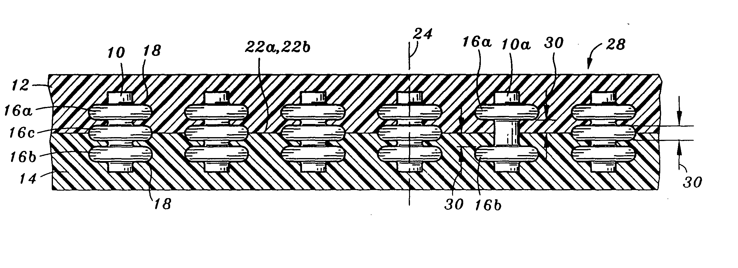
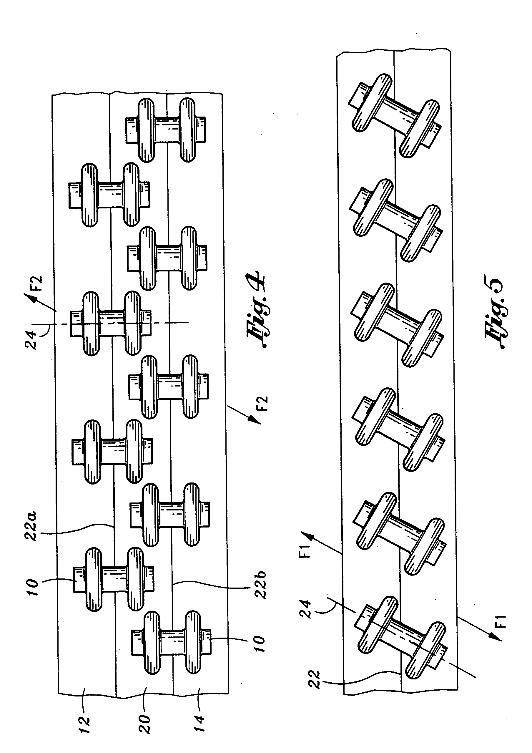
[0014] In another aspect of the present invention, a longitudinal axis of the z-pin may be aligned with an applied force which acts upon the attached layers. For example, if the direction of the applied force is angled seventy degrees from the interface surfaces of the first and second layers, then the preferable orientation of the longitudinal axis of the z-pins is seventy degrees from the interface surfaces. In this regard, the applied force may act upon the z-pins primarily in a tensile direction to thereby reduce stress concentrations that may result from the z-pin at the interface surfaces of the first and second layers. The following example will better illustrate the reason for stress concentrations at the interface surfaces of the first and second layer when the longitudinal axes of the z-pins are not aligned with the applied force. In particular, if the above example was altered such that the longitudinal axis of the z-pins were perpendicular to the interface surfaces of the first and second layer then the applied force may create not only a tensile load on the z-pins but additionally a moment on the z-pin. This moment may bend or flex the z-pins so as to create a
deformity at a
diameter of the z-pin located at the interface surfaces of the first and second layers. The
deformity of the
diameter of the z-pin may be an expansion or contraction depending on the location about the diameter to thereby press up against the interface surfaces of the first and second layers. In sum, aligning the longitudinal axis of the z-pin with the applied force may reduce the
stress concentration between the z-pin and the interface surfaces of the first and second layer which accordingly increases the ability to control the reliability of the failure mode of the joint, first, and second layers.
[0015] In another aspect of the present invention, the materials the z-pins are manufactured from may be chosen as a function of the material from which the first and second layers are manufactured. For example, the coefficient of
thermal expansion (CTE) of the z-pin may be less than or equal to the CTE of the first and second layers. In this situation, when the CTEs are equal to each other, the physical dimensions of the z-pins may expand or contract in one-to-one proportion with respect to the physical dimensions of the first and second layers, and more particularly, may expand or contract in one to one relationship with
mating surfaces which receive the z-pins. The first and second layers define the
mating surfaces as a depression which are sized and configured to receive the z-pins. In this regard, as flange sections of the z-pins expand as the layers and z-pins are heated, the respective
mating surfaces which receive that particular z-pin may appropriately expand. As such, the pressure between the flange sections and the mating surfaces may remain constant as the attached two layers are cycled through a heat and cool cycle. In the situation where the axial or longitudinal CTE of the z-pin is less than the z direction CTE of the first and second layers, the attached layers may expand at a greater rate compared to the z-pin. In this case, the pressure at the joint mating surface is increased as the combined first and second layers with embedded z-pins are heated, and decreased as the temperature of the first and second layers is reduced. In sum, the unique relationship between the CTE of the z-pin and the CTE of the first and second layers provide the specific
advantage of allowing the control of joint
interface pressure by maintaining, increasing or decreasing the initial pressure therebetween.
[0017] In another embodiment of the present invention, the first layer may have a depression sized and configured similarly to a corresponding flange section formed on the second layer. The second layer may have a nub formed on the interface surface similarly to a flange section of the z-pin. Additionally, the nub and the second layer may be manufactured at a unitary unit. Thereafter, the nub may be embedded within the depression of the first layer. The unitary nature of the nub and the second layer provides an additional or specific
advantage of controlling the failure mode between the first and second layers. For example, the pull out force of the nub from the depression of the first layer may be less than a
delamination force required to break off the nubs from the second layer. In this regard, the failure of the attachment between the first and second layers may be controlled such that the failure occurs in the first layer. Hence, the first layer may be designed as a replaceable layer, whereas the second layer may be designed as a sturdy non-replaceable second layer. This concept of making one of two parts a replaceable part is similar to a screw and screw hole design where failure is preferably at the threads of the screw instead of the threads of the screw hole because replacing a screw is easier and less costly compared to replacing the structure the screw hole is formed.

