
Anastomosis device and method

a technology of anastomosis and a tube is applied in the field of surgical instruments and methods, which can solve the problems of population mortality of 5 years and congestive heart failure, and achieve the effects of reducing trauma, pain, and recovery tim

Inactive Publication Date: 2005-02-24
BATTELLE MEMORIAL INST
View PDF8 Cites 45 Cited by
  • Summary
  • Abstract
  • Description
  • Claims
  • Application Information

AI Technical Summary

Benefits of technology

[0013] For example, this aspect of the present invention can be used for the treatment of the enlargement of the left ventricle that results from a variety of heart ailments. This condition leads to congestive heart failure with a median population mortality of 5 years. The present invention can be utilized to reduce the volume of the left ventricle in order to reduce stress in the myocardium and increase the ejection fraction of the heart. In utilizing this aspect, a diaphragm can be deployed by a catheter into the left ventricle of the heart, creating two separate chambers and reducing the overall volume.
[0016] The present invention is adapted to minimally invasive techniques, thus reducing the trauma, risks, recovery time, and pain that accompany current open-chest techniques.

Problems solved by technology

This condition leads to congestive heart failure with a median population mortality of 5 years.

Method used


Image

  • Anastomosis device and method
  • Anastomosis device and method
  • Anastomosis device and method

Examples


Embodiment Construction

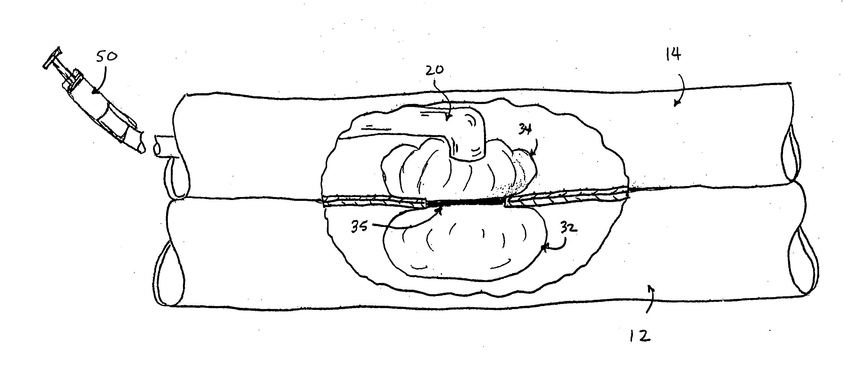
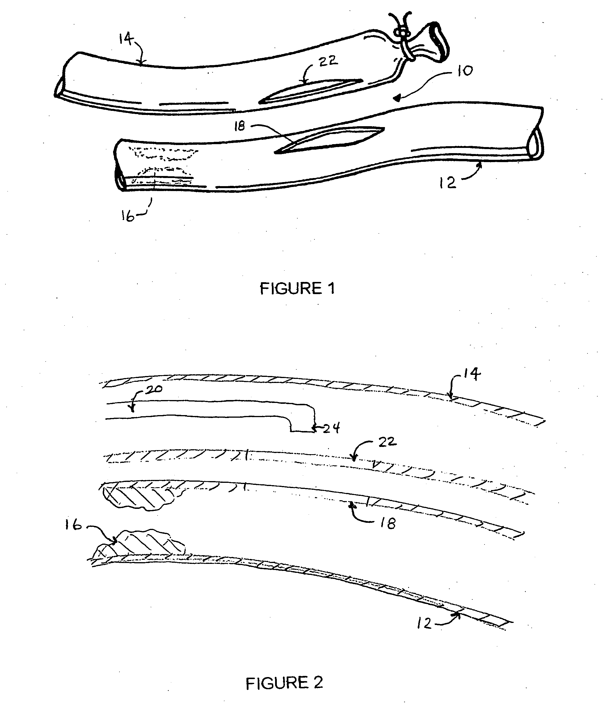
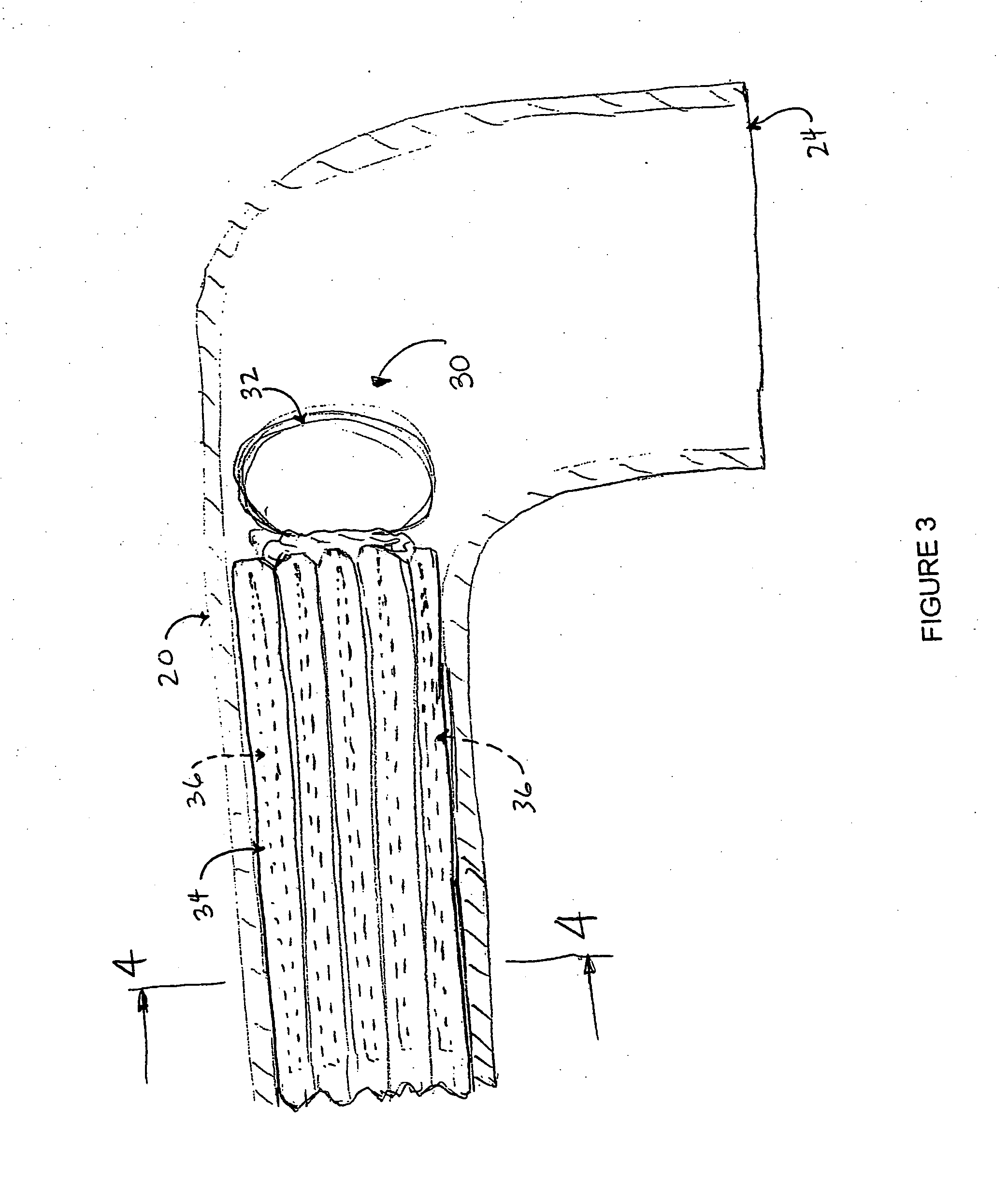
[0031] Turning now to the drawings, wherein the showings are for purposes of illustrating the preferred embodiments of the invention only and not for limiting the same, FIG. 1 shows an anastomotic site 10 involving a first vessel such as an artery 12 and a second vessel such as a graft 14. The artery 12 may be, for example, a coronary artery containing a stenosis 16 and the graft 14 may be, for example, a harvested vein or artery, or a synthetic vascular graft material such as expanded polytetrafluoroethylene (ePTFE) or the like. The location of one or more anastomotic sites are selected to bypass the blockage 16 and restore a physiologic blood flow to the areas downstream therefrom.

[0032] A longitudinal incision 18 is defined in the artery 12 at the intended anastomotic site 10, for example, by surgically exposing or accessing the artery and cutting. Alternatively, a blade or other means for forming the incision 18 can be advanced to the anastomotic site 10 intraluminally in a cat...


PUM


Abstract

An apparatus for treating a heart includes a housing member having a plurality of elongate channels defined therein and is movable between a first collapsed position and a second expanded position. A tissue attachment member is positioned in each channel. In one aspect, the apparatus is adapted for performing an anastomosis and includes a housing member having a plurality of elongate channels defined therein and which is movable between a fist collapsed position and a second expanded position. A surgical clip is positioned in each channel. A clip deployment mechanism projects the clips from their respective housings and a registration member approximates and aligns the first and second tubular structures. In a further aspect, helical barbs are movably affixed within sleeves formed on a sheetg of biocompatible material adapted for placement within a heart ventricle. Methods for treating a heart and reducing the volume of a heart ventricle are also provided. In a still further aspect, helical barbs provide attachment for patches for closure of a wound site or for suturing of a site needing closure. In yet another aspect of the invention, the helical barbs provide an attachment regine for implantable devices, as a well as a means to deliver medically efficacious materials to chosen sites with secure means. The helical device of the present invention further serves as a stent.

Description

FIELD OF THE INVENTION [0001] The present invention relates generally to the art of surgical instruments and methods and, in particular, to an improved apparatus and method for performing an anastomosis or surgical connection between tubular structures or vessels. The present invention finds particular application in the anastomotic joining of vascular tissue for the purpose of bypassing an occluded or diseased section of a blood vessel, such as a coronary artery, and will be described with particular reference thereto. However, it will be recognized that the present invention is amenable to anastomosis in general. The present invention further has broader applications in many different environments, such as securing patches for the noninvasive correction of intestinal perforations, deep hole wound closures, and others. The present invention has still further applications in the medical field, such as in affixing medical devices to tissues, attaching biological microelectromechanica...

Claims


Application Information

Patent Timeline
IPC IPC(8): A61BA61B17/00A61B17/064A61B17/08A61B17/11A61B17/115A61B17/22A61M31/00
CPCA61B17/0644A61B17/11A61B17/115A61B17/1155A61B2017/00544A61B2017/22054A61B2017/00867A61B2017/0649A61B2017/1103A61B2017/1135A61B2017/00557
Inventor GLEESON, JAMES BBRESLER, HERBERT SKELLEY, BRIAN C
Owner BATTELLE MEMORIAL INST
Learn More