
Method of adaptive interactive learning control and a lithographic manufacturing process and apparatus employing such a method

a learning control and interactive technology, applied in the field of adaptive interactive learning control and lithographic manufacturing process and apparatus employing such a method, can solve the problems of limited performance of ilc in the context of position-dependent dynamics, problem of motion tracking on different positions, wide use of industrial applications, etc., to achieve less potential and improve tracking performance

Inactive Publication Date: 2005-02-24
ASML NETHERLANDS BV
View PDF4 Cites 62 Cited by
  • Summary
  • Abstract
  • Description
  • Claims
  • Application Information

AI Technical Summary

Benefits of technology

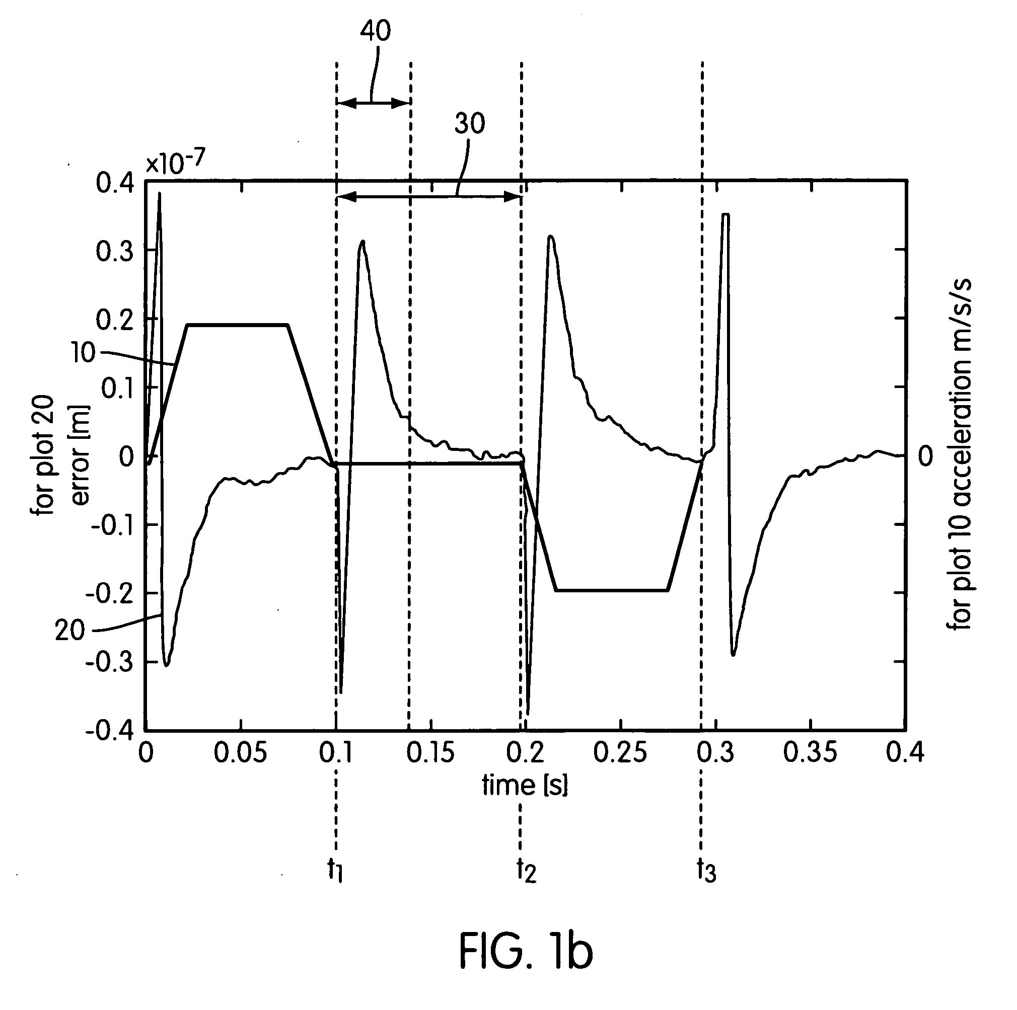
[0017] The learning process has therefore less potential for improving tracking performance for the time-instants outside these intervals, where it only leads to amplification of noise, thus, the filter in the learned feed-forward path is adapted accordingly, to the effect that ILC is concentrated only within the areas of the setpoint trajectory where the high energy signals are concentrated.

Problems solved by technology

Although ILC leads to a good tracking performance, several issues remain that prevent it from being widely used for industrial applications.
Experience with ILC algorithms applied to various motion systems has shown that ILC has limited performance within the context of position-dependent dynamics.
Further, understanding and controlling position-dependent dynamics (seen as a non-linear system) while motion tracking on different positions is a problem.
Furthermore, ILC does not account for setpoint trajectory changes.
Despite a very good tracking error performance, completion of the ILC procedure and the implementation of a suitable feed-forward signal, which corresponds to a certain setpoint profile costs time.
38(42), 2002”, but they have not yet led to a satisfactory solution.
Finally, noise amplification can be a problem.
For wafer scanning systems, the fact that the learned feed-forward signal is dependent on the setpoint constitutes the main drawback, since the setpoint is related to the frequently changing size of the die, which is illuminated in the scanning process.

Method used


Image

  • Method of adaptive interactive learning control and a lithographic manufacturing process and apparatus employing such a method
  • Method of adaptive interactive learning control and a lithographic manufacturing process and apparatus employing such a method
  • Method of adaptive interactive learning control and a lithographic manufacturing process and apparatus employing such a method

Examples


Embodiment Construction

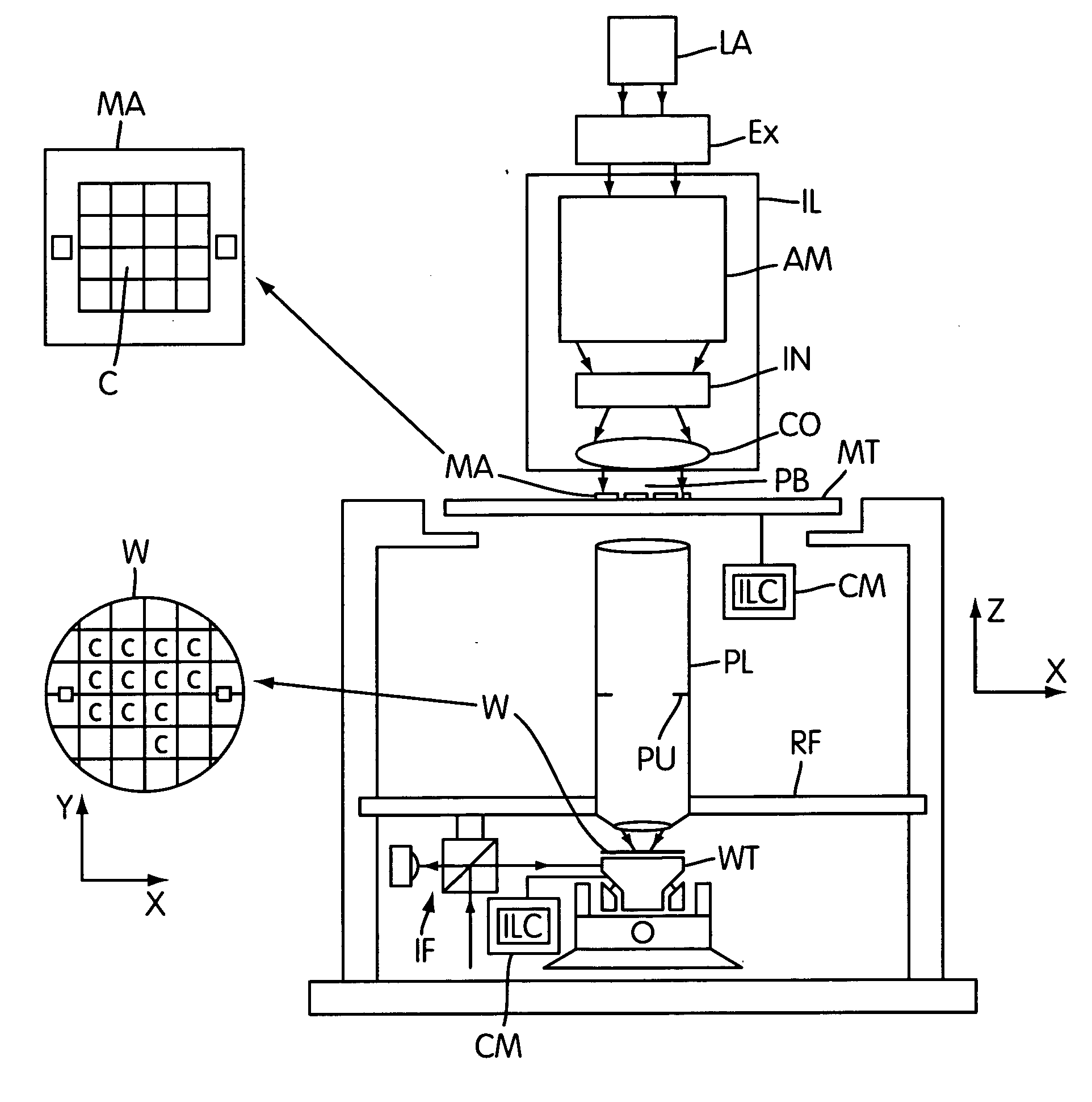
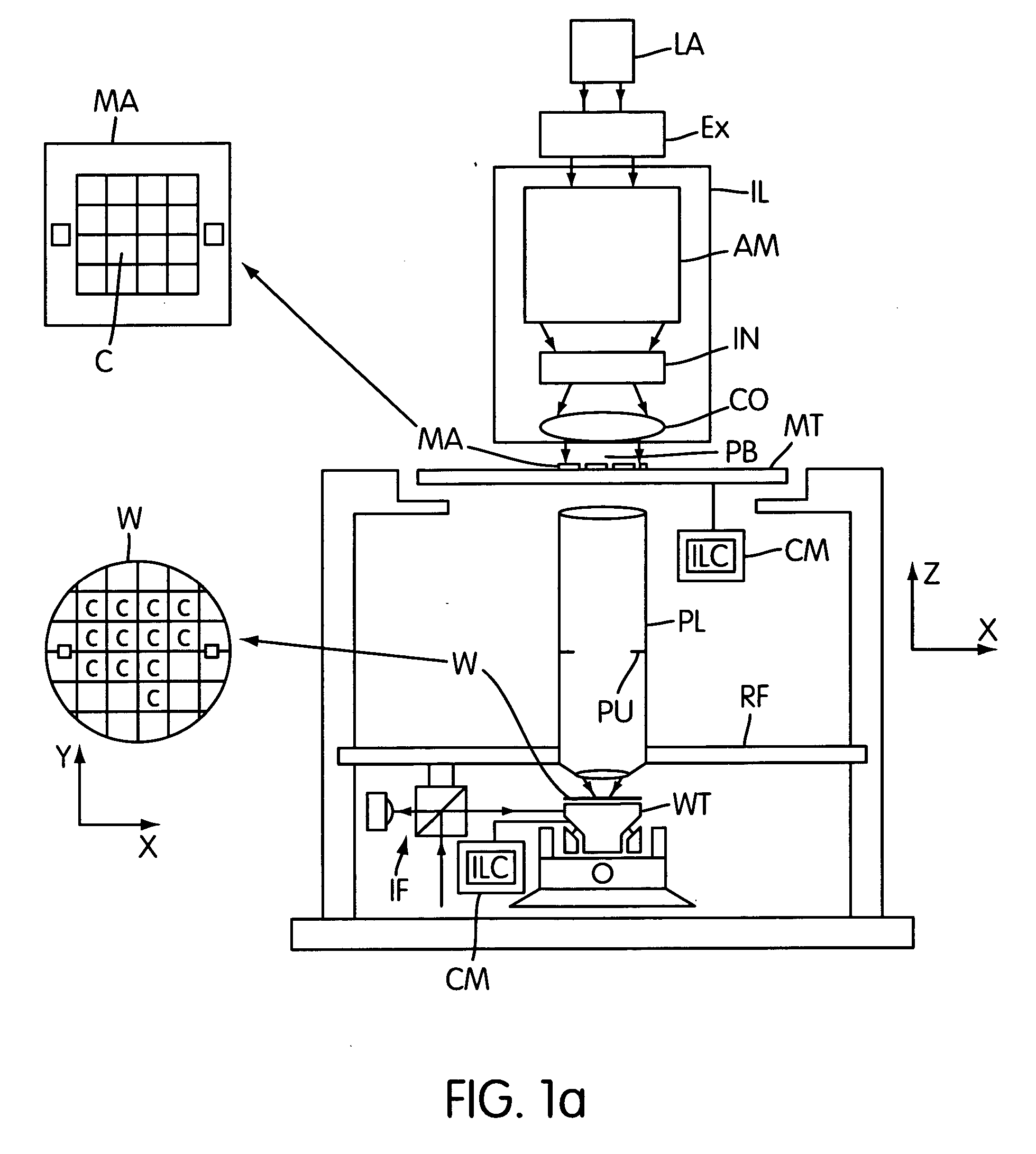
[0035]FIG. 1a depicts a lithographic projection apparatus embodying the invention. The invention is not however limited in this respect. The present invention has application to any process or system, which is to be controlled over a setpoint trajectory.

[0036] In the following detailed description, which references lithographic systems as an example of an application of the present invention, the following remarks should be kept in mind: the term “patterning device” as here employed should be broadly interpreted as referring to a device that can be used to impart an incoming radiation beam with a patterned cross-section, corresponding to a pattern that is to be created in a target portion of the substrate; the term “light valve” can also be used in this context. Generally, the pattern will correspond to a particular functional layer in a device being created in the target portion, such as an integrated circuit or other device (see below). Examples of such patterning devices include...


PUM


Abstract

By applying time-frequency analysis to a given standard iterative learning control or ILC an adaptive filter for the learned feed-forward loop is designed. This time varying filter varies according to the momentary frequency content of the error signal and allows to discriminate between areas of deterministic and stochastic error. Its application results in selective application of ILC to those intervals where error signals of high level are concentrated and allows application of a single ILC acquisition to different setpoint trajectories. The adaptive filter finds particular use in lithographic scanning systems where it is used for varying scan length.

Description

BACKGROUND OF THE INVENTION [0001] 1. Priority Information [0002] This application claims priority from European Patent Application No. 03077461.6, filed Aug. 6, 2003, herein incorporated by reference in its entirety. [0003] 2. Field of the Invention [0004] The invention concerns a method of controlling a system or process using a learned feed-forward signal, a control system and a lithographic projection apparatus. [0005] 3. Description of the Related Art [0006] The essential steps in the manufacturing process of integrated circuits (ICs) are performed by lithographic machines called wafer scanners or wafer steppers. Important modules of these machines are the wafer and reticle stages. According to current state of the art, a wafer stage is normally a motion system, which positions the silicon wafer with respect to the illumination optics with high precision. As ICs are becoming smaller, the required precision increases proportionally. In order to meet positioning specifications th...

Claims


Application Information

Patent Timeline
IPC IPC(8): G03F7/20G06F19/00H01L21/66
CPCG03F7/70358H01L22/20G03F7/70725G03F7/70491
Inventor ROTARIU, ANDREEA IULIANAELLENBROEK, ROGIERSTEINBUCH, MAARTENVAN BAARS, GREGOR EDWARD
Owner ASML NETHERLANDS BV
Learn More