
Method for putting color to glass or erasing color from colored glass

a technology of colored glass and color, applied in the field of putting color to glass or erasing color from colored glass, can solve the problems of difficult to precisely regulate the focal point of laser light along the depth of the transparent substrate, the object is limited to a transparent material, and the object has cracks

Inactive Publication Date: 2005-03-03
CENT GLASS CO LTD +1
View PDF15 Cites 25 Cited by
  • Summary
  • Abstract
  • Description
  • Claims
  • Application Information

AI Technical Summary

Benefits of technology

The present invention provides methods for putting color on glass and erasing color from colored glass. The first method involves using a laser to create non-bridging oxygen holes in the glass to put color on it. The second method involves using a high energy light to create silver particles in the glass to put color on it. The third method involves using a laser to selectively heat and turn a colored portion of the glass into a colorless portion. These methods allow for the creation of fine marks on glass without adding damage.

Problems solved by technology

In this method, the laser convergence may cause the object to have cracks if the object is glass.
In this method, it may be difficult to precisely regulate the focal point of the laser light in a direction along the depth of the transparent substrate.
In this method, the object is limited to a transparent material since the marking is made by cracks of the inside of the object.
The resulting colored glass, however, may become inferior in strength and transparency.
Furthermore, such color is not stable under normal temperatures and gradually fades away.
Therefore, X-ray irradiation is not a reliable measure for obtaining colored glass.

Method used


Image

  • Method for putting color to glass or erasing color from colored glass
  • Method for putting color to glass or erasing color from colored glass
  • Method for putting color to glass or erasing color from colored glass

Examples


example 1

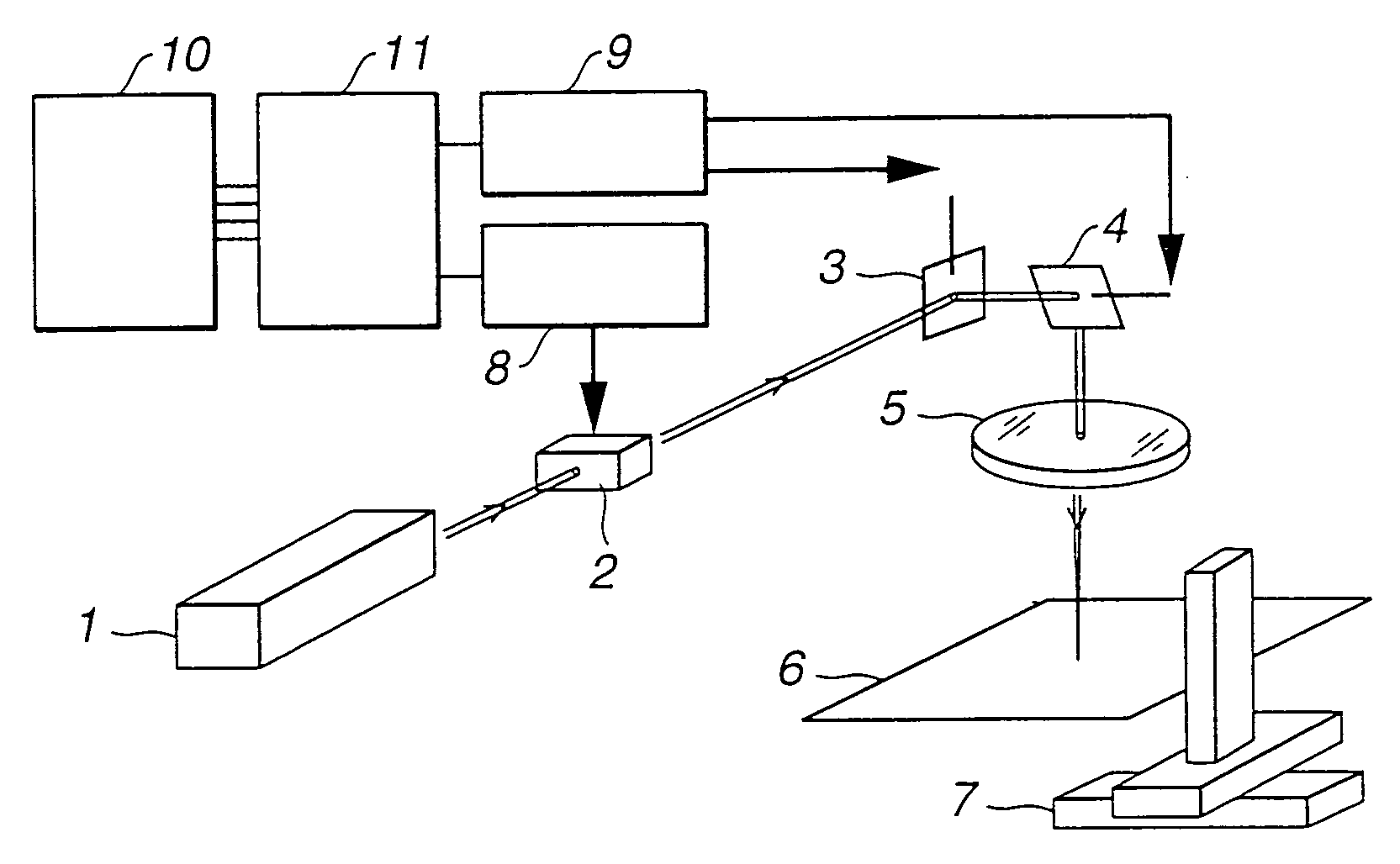
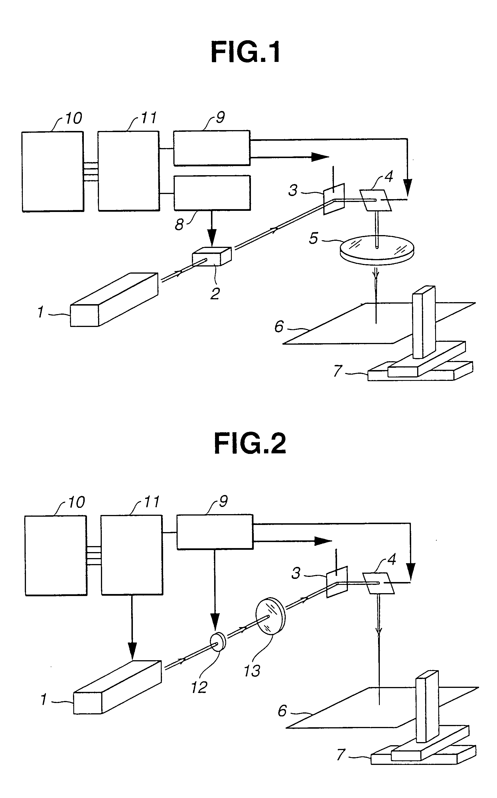
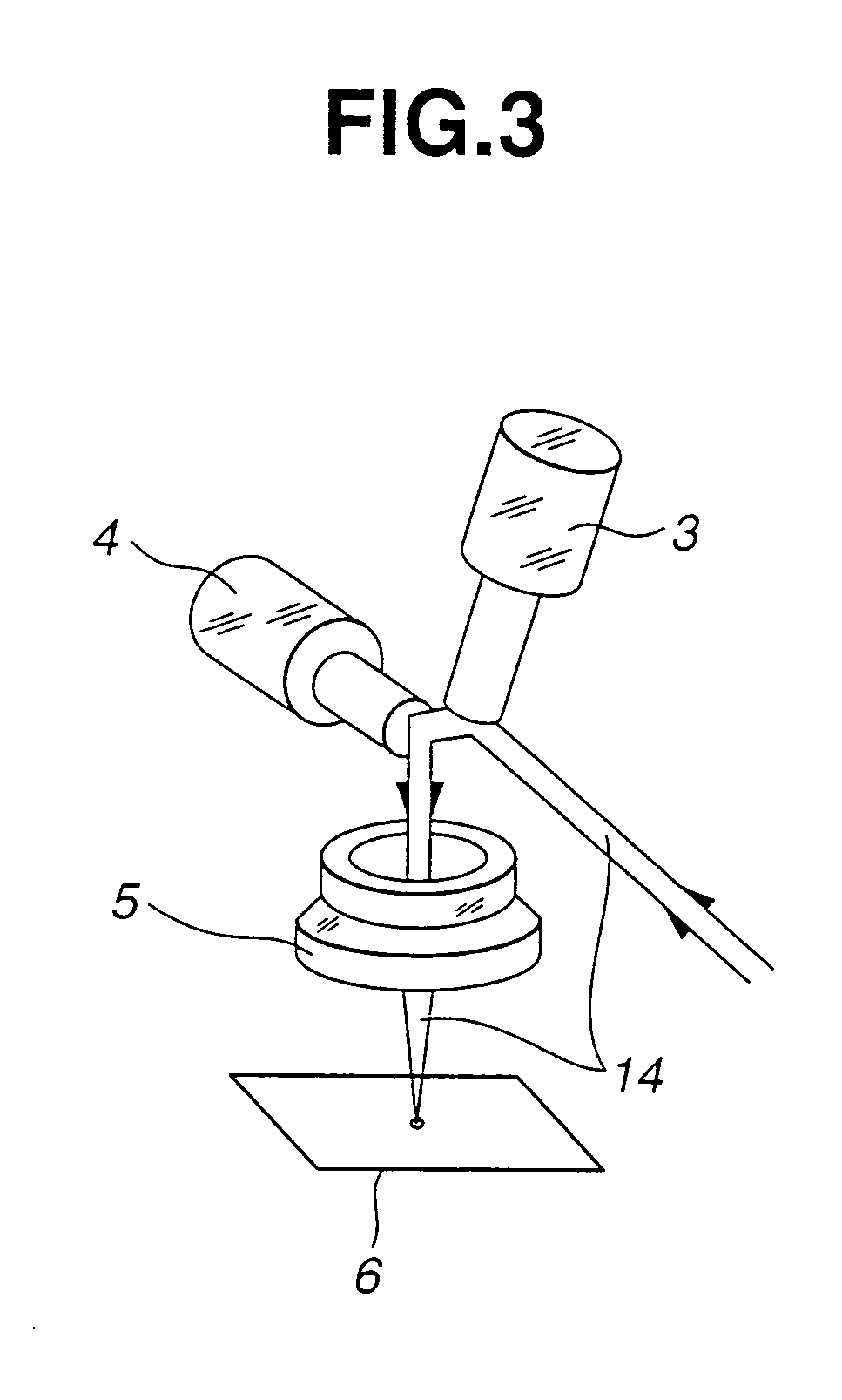
[0066] The second laser irradiation apparatus (shown in FIG. 2) was used for putting a color to a silicate glass containing non-bridging oxygen in its structure. A laser light was oscillated by the UV pulsed laser oscillator 1 to have a wavelength of 355 nm, a pulse width of 20 ns, a pulse energy of 117 μJ, an average output of 2.9W, and a repetition frequency of 25 kHz. This laser light was condensed by the condenser lens 2 into a laser beam, and this laser beam was reflected by the X-mirror 3 and the Y-mirror 4 toward the target 6. The target 6 was a transparent silicate glass plate having a thickness of 6 mm and widths of 100 mm and having a chemical composition of 72 wt % SiO2, 16 wt % Na2O, 10 wt % CaO, and 2 wt % Al2O3. The silicate glass plate was scanned with the laser beam with a scanning speed of 250 mm / sec.

[0067] The scanning was conducted by suitably switching on and off the Q switch built in the UV pulsed laser oscillator, by regulating the angles of the X-mirror 3 and...

example 2

[0072] The second laser irradiation apparatus (shown in FIG. 2) was used for putting a color to a silver-ion-containing glass. A laser light was oscillated by the carbon-dioxide laser oscillator 1 to have a wavelength of 10600 nm, a repetition frequency of 10 kHz or 20 kHz, and an average output of 1W, 2W, 5W, 10W or 20W. This laser light was condensed by the condenser lens 12 into a laser beam, and this laser beam was reflected by the X-mirror 3 and the Y-mirror 4 toward the target 6.

[0073] The target 6 was prepared as follows. At first, there was prepared by float method a soda-lime glass substrate (thickness: 5 mm; widths: 100 mm) having a chemical composition of 72 wt % SiO2, 16 wt % Na2O, 10 wt % CaO, and 2 wt % Al2O3. Then, the glass substrate was immersed for 5 min or 15 min in a fused salt (prepared by mixing 1 part by mol of AgNO3 with 4 parts by mol of NaNO3) heated at 590K (317° C.), thereby replacing Na ions of the glass surface with silver ions.

[0074] The target 6 (si...

example 3

[0080] The second laser irradiation apparatus (shown in FIG. 2) was used for putting a color to a silver-ion-containing glass. A laser light was oscillated by the UV pulsed laser oscillator 1 to have a wavelength of 355 nm, a pulse width of 20 ns, a pulse energy of 80 μJ, an average output of 2W, and a repetition frequency of 25 kHz. This laser light was condensed by the condenser lens 12 into a laser beam, and this laser beam was reflected by the X-mirror 3 and the Y-mirror 4 toward the target 6.

[0081] The target 6 was prepared in the same manner as that of Example 2, except in that the immersion was conducted for 1 hr.

[0082] The target 6 (silver-ion-containing glass) was scanned with the laser light to have a line width of 10 μm with a scanning speed of 250 mm / s, thereby drawing a rectangle (dimensions: 9 mm×15 mm) of a yellow color.

[0083] It was possible to draw a plurality of rectangles at a constant interval by horizontally moving the XYZ-stage 7.

[0084] Furthermore, it is p...


PUM

PropertyMeasurementUnit
wavelengthaaaaaaaaaa
distanceaaaaaaaaaa
wavelengthaaaaaaaaaa

Abstract

The invention relates to a method for putting color to glass by irradiating a silicate glass, containing a non-bridging oxygen in its structure, with a laser light, thereby forming a non-bridging oxygen hole center therein to put a color to the glass. The invention further relates to a method for putting color to glass by irradiating a silver-ion-containing glass with a high-energy light, thereby forming silver particles in the glass through aggregation of silver ions to put a color to the glass. The invention further relates to a method for erasing color from colored glass by irradiating a colored portion of a glass with a laser light to selectively heat the colored portion by using a laser irradiation apparatus comprising (a) a laser oscillator, (b) a light modulator, (c) a condenser lens mounted on a linear translator, (d) an objective lens, and (e) a galvanometer mirror.

Description

BACKGROUND OF THE INVENTION [0001] The present invention relates to a method for putting a color to glass or erasing color from colored glass by laser irradiation. [0002] There are several proposals for marking glasses by laser irradiation (see Japanese Patent Laid-open Publications 2-242220, 3-124486, 4-71792, and 11-156568). [0003] Japanese Patent Laid-open Publication 2-242220 discloses eyeglass frame parts (made of a laser absorbing transparent plastic) of which inside has a scorch pattern formed by laser irradiation. [0004] Japanese Patent Laid-open Publication 3-124486 discloses a laser marking method in which a laser light is converged at an interior of an object. In this method, the laser convergence may cause the object to have cracks if the object is glass. [0005] Japanese Patent Laid-open Publication 4-71792 discloses another laser marking method in which a transparent substrate interior is selectively made opaque by focusing a laser light into the transparent substrate. ...

Claims


Application Information

Patent Timeline
Patent Type & Authority Applications(United States)
IPC IPC(8): C03C4/02C03C21/00C03C23/00
CPCC03C4/02C03C21/005C03C23/007B41M5/262C03C23/0025
Inventor YAMATE, TAKASHIITAKURA, NOBUYUKINISHIKAWA, SHINJITAMON, HIROYUKIUEMURA, HIROSHIKADONO, KOHEIAKAI, TOMOKOYAMASHITA, MASARUYAZAWA, TETSUOMORI, SHIGERUUTAGAWA, YASUSHISHENG, JIAWEI
Owner CENT GLASS CO LTD
Learn More