[0024] In view of the foregoing, it is among the objects and advantages of the present invention to provide an affordable and user-friendly apparatus to allow the sewing of patterns larger than the throat depth of a sewing machine. It is also an object /
advantage of the present invention to be
usable with a wide variety of existing and future hobby and professional quilting frames. It is also an object /
advantage of the present invention to be
usable with a wide variety of existing and future hobby and professional sewing machines of a wide range of throat depths. It is also an object /
advantage of the present invention to provide automatic,
continuous operation whereby the take-up roller is moved automatically without user
initiation to allow the sewing of patterns larger than the throat depth of a sewing machine. It is also an object / advantage of the present invention to provide a lightweight apparatus which is portable and can be used with portable quilting frames. It is also an object / advantage of the present invention to be
usable with a wide variety of computer controlled, manually controlled (free hand), or X-Y template-guided sewing machine carriages provided by the manufacturers of hobby and professional quilting frame or by third parties.
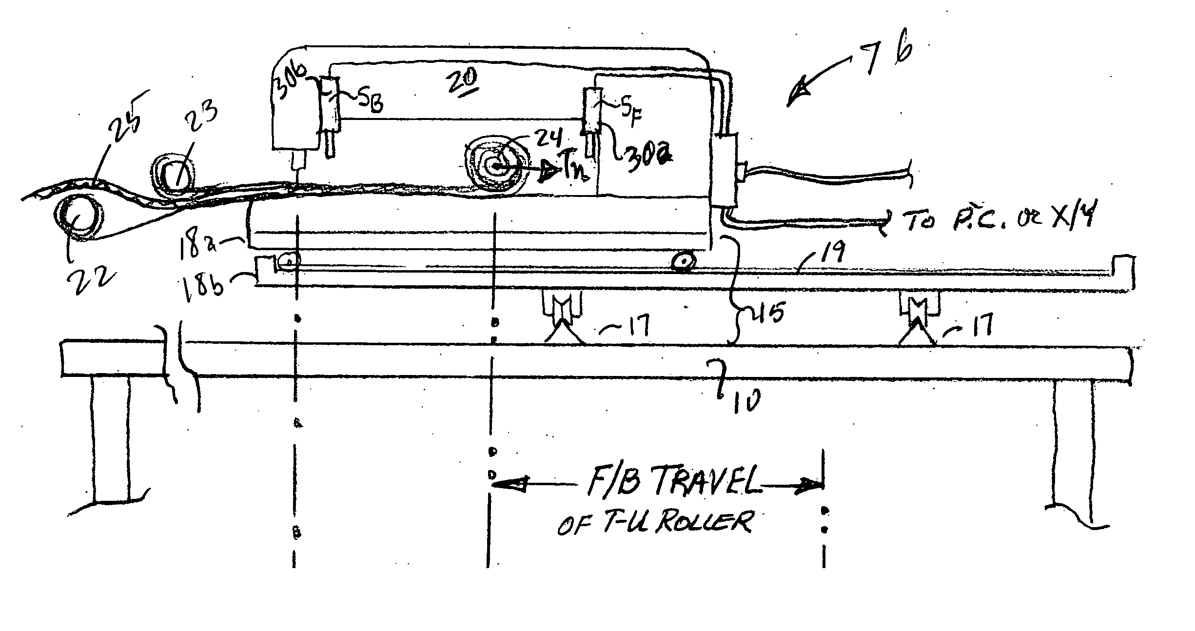
[0025] Consistent with the foregoing objects, and in accordance with the present invention as embodied and broadly described herein, a method and apparatus are disclosed in the presently preferred embodiment of the present invention comprising a powered take-up roller journaled in one or more movable motorized
carriage assemblies (and where only one motor is used on one end of the take-up roller, an opposed movable take-up roller idler
carriage assembly); two opposed end plates having tracks or sliding surfaces mounted thereon receiving the roller carriage assemblies; a
sensor system for initiating take-up roller rotation, an automatic tension
system;
control electronics for use with a quilting frame of any dimension; and a sewing machine of any throat depth.
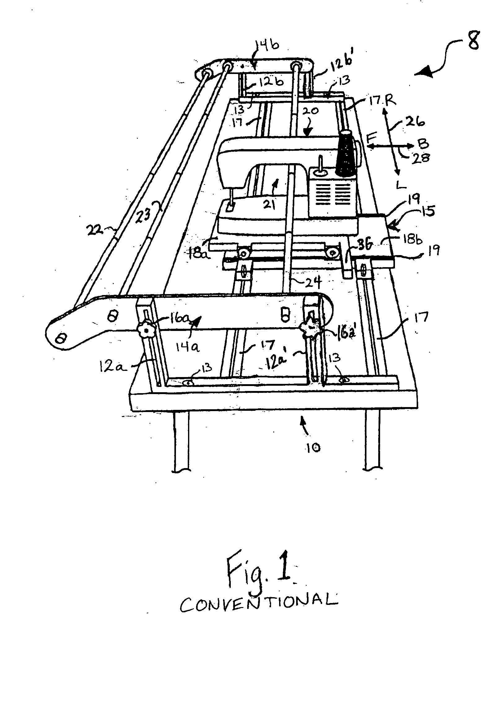
[0026] In addition, the inventive VSA system can be integrated with quilting
application software to provide PC operated quilting with automatic VSA. The apparatus and method provides automatic, powered fore and aft (Forward / Backward)
lateral movement of the quilting frame's takeup roller while simultaneously rotating the take-up roller
clockwise or counter-
clockwise to allow take-up or payout (furling or unfurling) of fabric
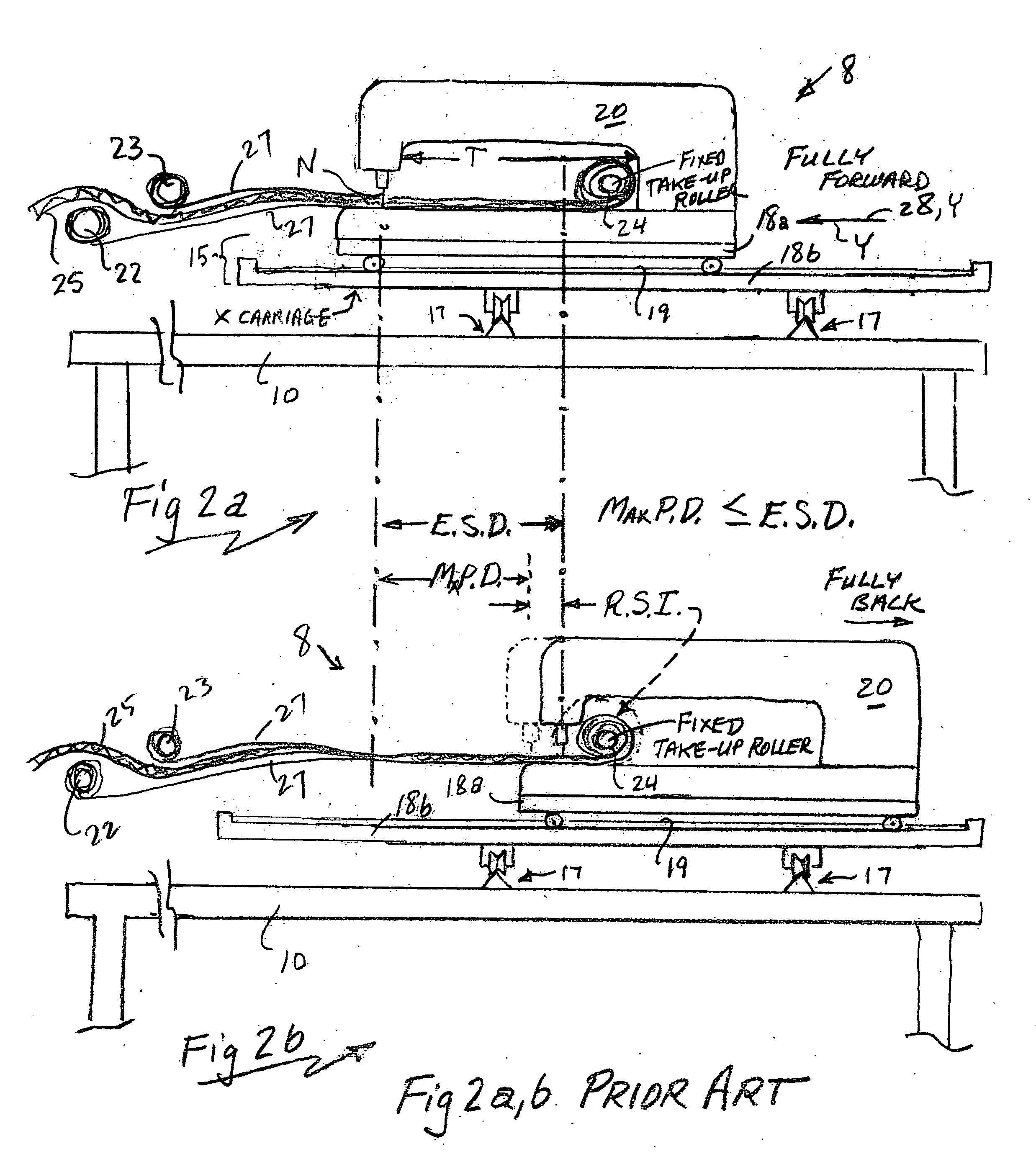
layers to provide a movable working area, called a Variable Sewing Area or VSA. The VSA permits increased lateral pattern coverage by means of conventional sewing machine carriages used with the quilting frame, while tension is simultaneously maintained on the fabric
layers stretched between the take-up roller and the payout roller or rollers. The prior art restriction on pattern depth caused by the combination of a fixed takup roller and limited sewing machine throat depth is substantially reduced or eliminated.
[0027] In one presently preferred embodiment of the present invention, the take-up roller may be configured in sections or telescoping to provide a wide range of quilt widths. In the alternative, it may be of any desired
fixed length. In any of these configurations, it may be square, round, elliptical or polygonal in cross-section. The take-up roller in any such configuration is attached at each end to a movable carriage
assembly. In the optional embodiment where a motor is used only at one end, the other end of the take-up roller is mounted to a movable idler carriage
assembly.
[0028] A tension device system is used at both take-up roller carriages to provide Backward tension on the movable motor and optional movable idler assembly carriages to maintain constant tension on the fabric layer or layers stretched between the fabric supply (payout) rollers of the quilting frame and the take-up roller. Tracks, rails or sliding surfaces may be used to facilitate the fore and aft
lateral movement of the movable motor carriage assembly and the idler assembly at each end of the take-up roller, independent of both the motorized rotation of the take-up roller and of the tensioning device(s). The corresponding tracks, rails or sliding surfaces preferably are mounted on each opposed end plate of the apparatus and preferably include at least a Back stop, and optionally also a Forward Stop, to limit movement of the take-up roller beyond an appropriate
working range. In the alternative, with simple reversal of parts, the tracks may be on the take-up roller motorized carriage and the idler carriage, and the wheels or other sliding members may be mounted on the end plates.
[0029] Continuing with a presently preferred embodiment, the movable motor carriage assembly comprises a
direct current reversible motor connected to a gear box with a projecting shaft (available in the marketplace as a complete pre-assembled unit, commonly known as gear head motors). Wheels are attached to the gear head motor assembly unit in an operative geometric array using commonly available fasteners; the wheels are preferably grooved to receive the guide tracks or rails secured to the end plates. Each end of the take-up roller is attached to the respective Left or Right motor assembly output shaft, optionally but preferably by means of a
coupling tube which fits over the gear box output shaft and is locked in place by means of a
set screw, removable pin, or the like. The other end of the
coupling tube slides into or over the tubular take-up roller and is locked in place by means of a
set screw or a removable pin.


