
System and method for removing deep sub-micron particles from water

a technology of deep submicron particles and water, which is applied in the direction of differential sedimentation, non-contaminated water treatment, treatment water, etc., can solve the problems of difficult treatment, large amount of sludge, and water recovery only reaching about 60%

Inactive Publication Date: 2005-03-03
IND TECH RES INST
View PDF2 Cites 50 Cited by
  • Summary
  • Abstract
  • Description
  • Claims
  • Application Information

AI Technical Summary

Benefits of technology

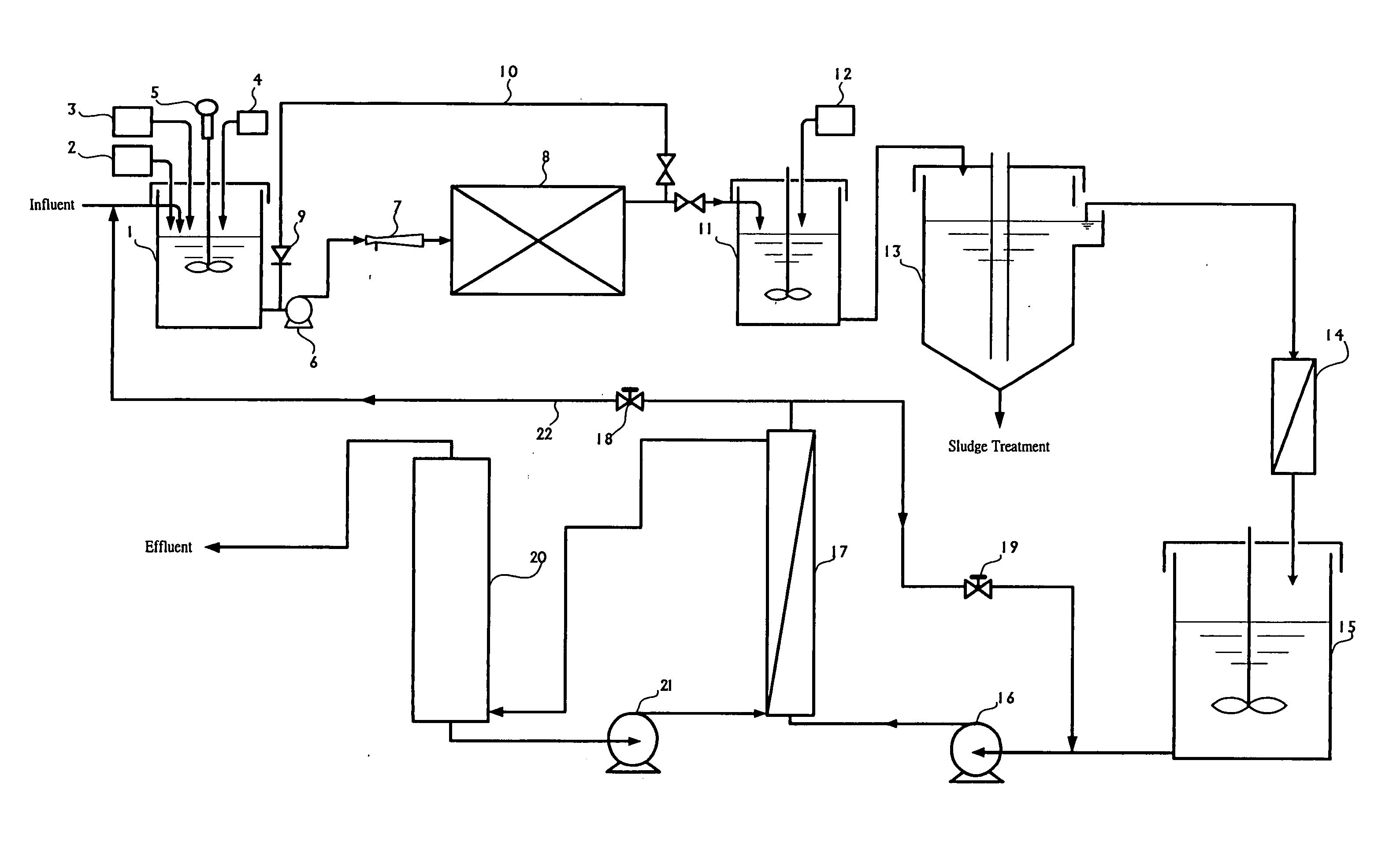
[0012] Preferably, the module of the present invention further comprises an air injector for providing a sufficient mixing between the effluent from said front adjustment tank and air prior to said effluent entering said electrocoagulation reaction tank.

Problems solved by technology

Therefore, “how to remove micro-pollutions” will be a key issue in elevating the production level of the next generation chips.
Due to the mass production of wafers in recent years, a large amount of waste water is produced and contains a high concentration of deep sub-micron particles, which is difficult to be treated, during grinding and dicing saw prior to the encapsulation operation of the chips.
While applied on the removal of deep sub-micron particles, the former methods require the use of a large amount of coagulants and flocculants to achieve the desired results, generating a relatively large amount of sludge, and the amount of water recovered can only reach about 60%.
However, a distillation method requires a massive energy consumption, which is not practically acceptable to the industry; and a membrane filtration method often faces the problems of membrane fouling and low production of water per membrane unit area.

Method used


Image

  • System and method for removing deep sub-micron particles from water
  • System and method for removing deep sub-micron particles from water

Examples


example 1

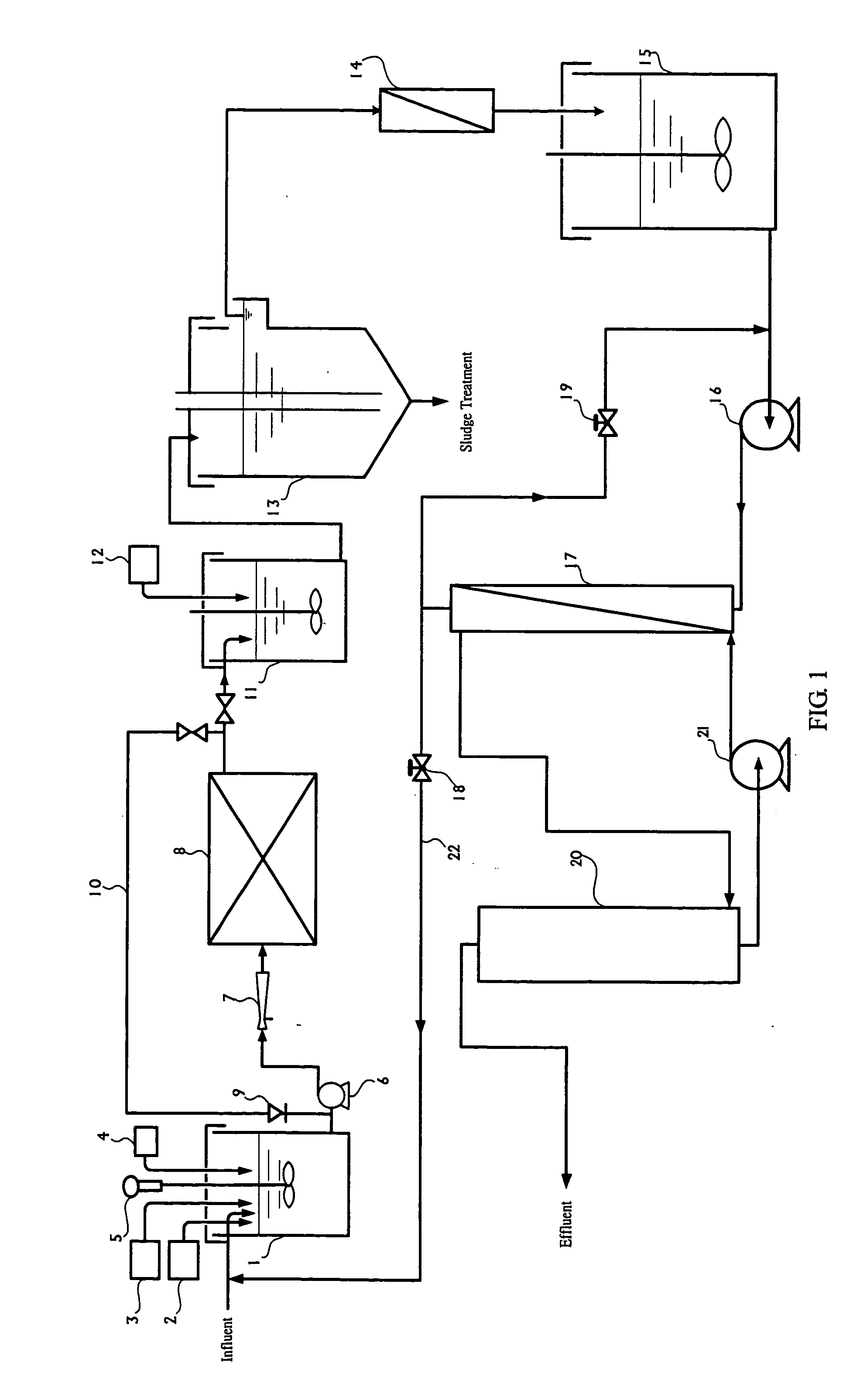
[0041] A module as shown in FIG. 1 was used to carry out an experiment on removing deep sub-micron particles from a CMP waste water containing about 0.2% of deep sub-micron particles.

[0042] The front adjustment tank adjusted the pH value of the waste water to 4 and the conductivity to 0.5 ms / cm. H2O2 was added into the waste water at a ratio of 1:0.005 (water:H2O2 aqueous solution). The current in the electrocoagulation reaction tank was controlled at 1 A. The recycled flow and the effluent were controlled so that the residence time of the waste water in the electrocoagulation reaction tank was maintained at 15 minutes. The rear adjustment tank adjusted the pH value of the effluent from the electrocoagulation reaction tank from 8.8 to 4.5. The residence time of the sedimentation reservoir was set to be 3 hours. After the abovementioned steps, the effluent contained 0.003% of deep sub-micron particles, and had a removal rate of 98.5%. The effluent was processed by an ultra-filtratio...


PUM

PropertyMeasurementUnit
Ratioaaaaaaaaaa
Heightaaaaaaaaaa

Abstract

The present invention discloses a process and an apparatus for removing deep sub-micron particles from water. The invented process includes adjusting pH value and conductivity, adding an oxidation agent, performing an electro coagulation reaction / an electro-oxidation reaction, and performing a flocculation sedimentation, etc. The invented apparatus includes a front adjustment tank for adjusting the properties of waste water, wherein the adjustment includes a pH adjustment, an electrolyte adjustment, or an oxidant addition, etc.; an electrocoagulation reaction tank receiving water from the front adjustment tank and having pairs of separated electrodes, one of the electrodes being made of iron; a rear adjustment tank for adjusting pH value of the effluent of the electrocoagulation reaction tank; and a sedimentation reservoir for providing the resulting pH-adjusted, sedimentary floccule-containing water from the rear adjustment tank with a sufficient residence time in said sedimentation reservoir, so that floccules and sedimentation are formed therein.

Description

FIELD OF THE INVENTION [0001] The present invention relates to a process and a device for removing deep sub-micron particles from water, particularly the removal of deep sub-micro particles in waste water discharged from the chemical mechanical polishing, grinding and dicing saw of wafers in the semiconductor fabrication and encapsulation processes. BACKGROUND OF THE INVENTION [0002] Along with the trend of highly integration and miniaturization of line width in the semiconductor, the influence on the mass production of wafers caused by the micro-pollutions of metals, micro particles and organic compounds in the ultra-pure water also increases dramatically. Therefore, “how to remove micro-pollutions” will be a key issue in elevating the production level of the next generation chips. In the removal of micro particles, the size of the micro particles concerned has decreased from the micron level to the deep sub-micron level. Therefore, the technology of removing deep sub-micron partic...

Claims


Application Information

Patent Timeline
IPC IPC(8): B01D17/12B03D1/14B03D3/02C02F1/00C02F1/38C02F1/44C02F1/463C02F1/467C02F1/66C02F1/72C02F1/74C02F9/00
CPCB03D1/1437B03D1/028C02F1/38C02F1/444C02F1/463C02F1/4672C02F1/66C02F1/722C02F1/74C02F9/00C02F2001/007C02F2103/04C02F2103/346C02F2209/05C02F2209/06C02F2209/40B03D1/1475B03D1/247B03D3/02
Inventor KIN, KONTSUTANG, HONG-SHIANG
Owner IND TECH RES INST
Learn More