

Four-link vehicle suspension system
a suspension system and four-link technology, applied in the direction of rigid suspensions, resilient suspensions, vehicle components, etc., can solve the problems of occupying a lot of space, reduce the torque around the effective centre, reduce the effect of unwanted “wind up” movements
- Summary
- Abstract
- Description
- Claims
- Application Information
AI Technical Summary
Benefits of technology
Problems solved by technology
Method used
Image

Examples
Embodiment Construction
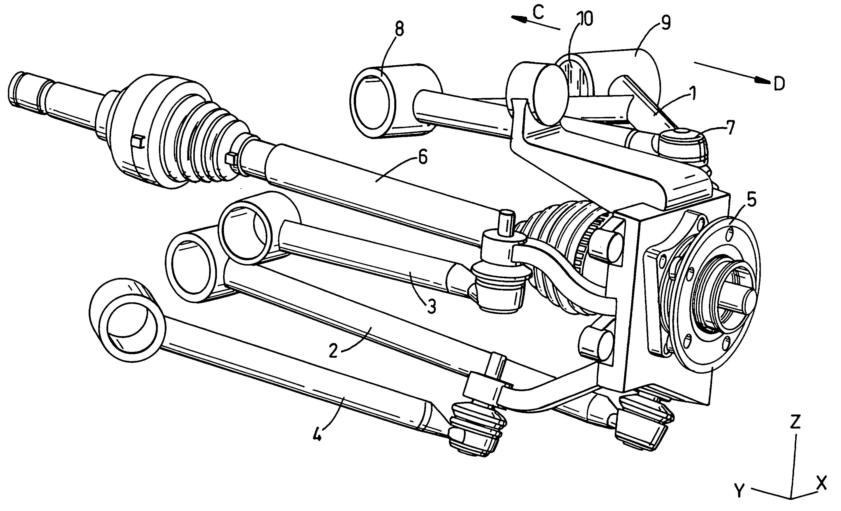
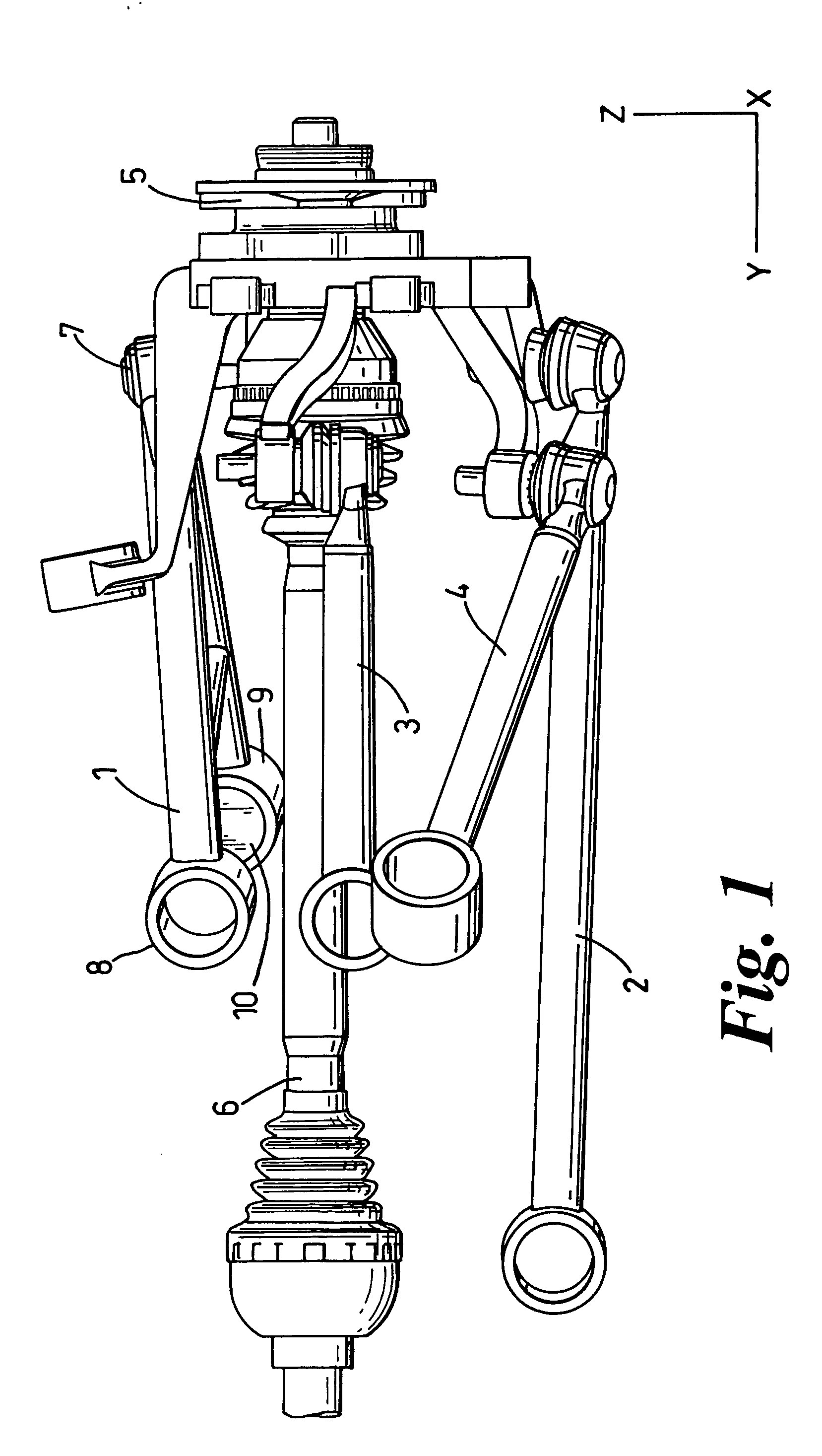
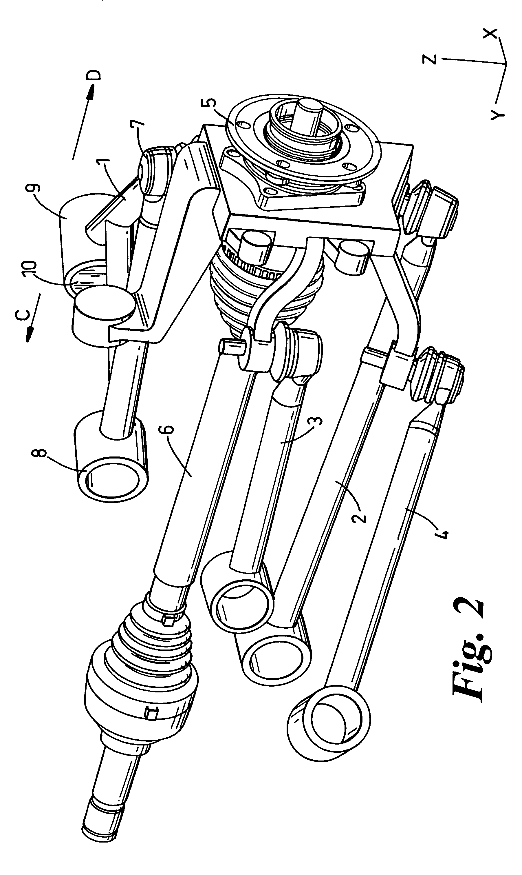
[0023] Referring to FIGS. 1 to 4, the rear suspension of this first embodiment comprises an upper transverse wishbone 1, a transverse toe link 2, a transverse control link 3 and a lower, forwardly extending longitudinal link 4. Each of these four links 1 to 4 is mounted between a wheel carrier 5 and the vehicle body or sub-frame (not shown). The wheel carrier 5 is attached to a rear axle 6 of the vehicle.
[0024] As is customary, the wheel carrier is also mounted to the vehicle body by means of some spring-loaded device (not shown) to allow vertical movement of the wheel carrier with respect to the vehicle body.
[0025] The upper wishbone 1 has a single mounting point 7 at one end where it is connected to the wheel carrier 5, and a pair of mounting points 8, 9 at its other end for connection to the vehicle body.
[0026] Referring to FIGS. 2 and 3, the rearward mounting point 9 is provided with a resilient bush 10 which has a comparatively soft spring rate in the inboard direction C and...
PUM
 Abstract
Description
Claims
Application Information