Actuator

a technology of actuators and rolling bearings, applied in the field of actuators, can solve the problems of not always desirable arrangement of double rolling bearings, relative large structural space to be provided, etc., and achieve the effects of no lateral structural space, high step-down ratio, and rapid and simple manner

Inactive Publication Date: 2005-03-03
SIEMENS AG
View PDF6 Cites 31 Cited by
  • Summary
  • Abstract
  • Description
  • Claims
  • Application Information

AI Technical Summary

Benefits of technology

[0004] It has surprisingly been shown that the actuator can be used to set relatively high step-down ratios, with virtually no lateral structural space being required. This is essentially achieved by an arrangement of housing, electric motor, planetary gear and the toothed rings which is realized on a common longitudinal axis z. Moreover, it is advantageous that the arrangement of rolling bearings can be entirely omitted. The installation can be carried out in a particularly rapid and simple manner if the particular number of teeth of the first toothed ring, of the second toothed ring and of the pinion, which is the sun wheel of the planetary gear, is an integral multiple of the double gearwheels.
[0005] One preferred refinement of the invention is that the number of teeth of the first toothed ring differs from the number of teeth of the second toothed ring by 3. This advantageously makes it possible to set relatively high step-up ratios for a wide variety of intended uses.
[0006] According to a further preferred refinement of the invention, provision is made for a disk-shaped mounting, which is fixed in the housing and has a central cutout for the pinion and at least one extension, to be arranged between the electric motor and the planetary gear and in which the extension engages in the electric motor. The disk-shaped mounting is, as a rule, a small circular plate with a central hole for the pinion for mounting the electric motor. The mounting is fixed in the housing and engages with its extension in the electric motor. It is advantageous here for the electric motor to have an additional mounting and, at the same time, it is avoided that the electric motor itself is exposed to rotational movements. As a result, the motor mounting can be formed in a simpler manner in terms of construction in the housing on the side lying opposite the pinion.
[0007] According to one preferred refinement of the invention, the second gearwheels are connected to each other on their side facing away from the electric motor at their axes of rotation via a bearing element which is in the form of an equilateral triangle. In this case, for example, a plate-like bearing element in the form of a disk can be used as the bearing element. This enables the double gearwheels to be securely mounted, with it being possible to reliably set a constant distance between the axes of rotation of the individual double gearwheels in a relatively simple manner.
[0008] According to a further refinement of the invention, provision is made for a total of three double gearwheels to be arranged. This enables a wide variety of step-down ratios to be set in a simple manner in terms of construction, so that the actuator can be used in a particularly versatile manner.
[0009] A further preferred refinement of the invention is for the second toothed ring to be part of a cup-shaped wheel which has, in the center of its side facing away from the electric motor, a further extension, which is connected to the part which is to be driven. The design of the second toothed ring as part of a cup-shaped wheel improves the running characteristics of the second toothed ring and therefore the transmission of force to the part which is to be driven.

Problems solved by technology

A disadvantage of the device described in DE 199 34 161 C2 is that a relatively large structural space has to be provided next to the actual swashplate mechanism for the arrangement of an electric motor, which, in many intended uses, is not needed.
Moreover, the arrangement of a double rolling bearing is not always desirable.

Method used


Image

  • Actuator
  • Actuator
  • Actuator

Examples


Embodiment Construction

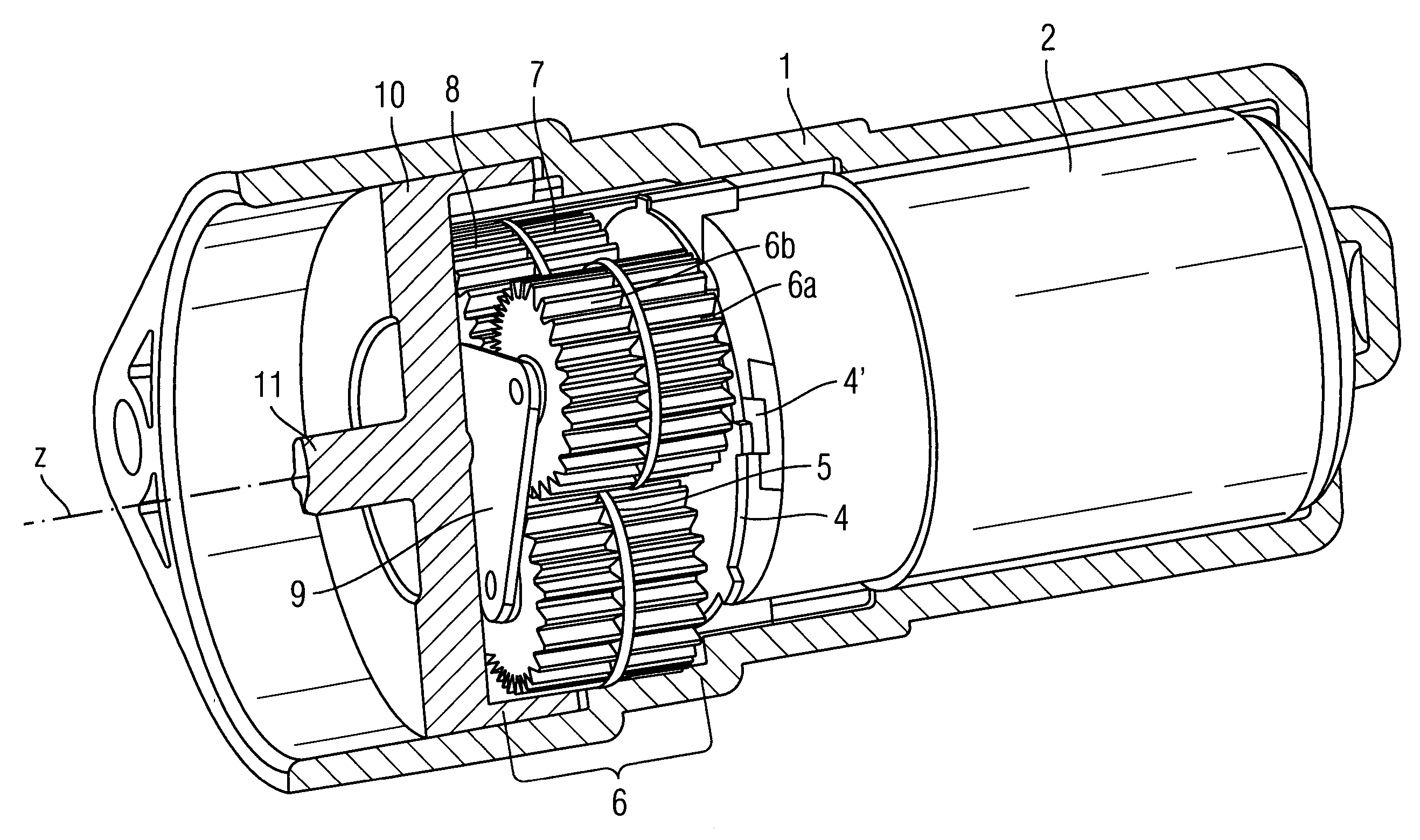
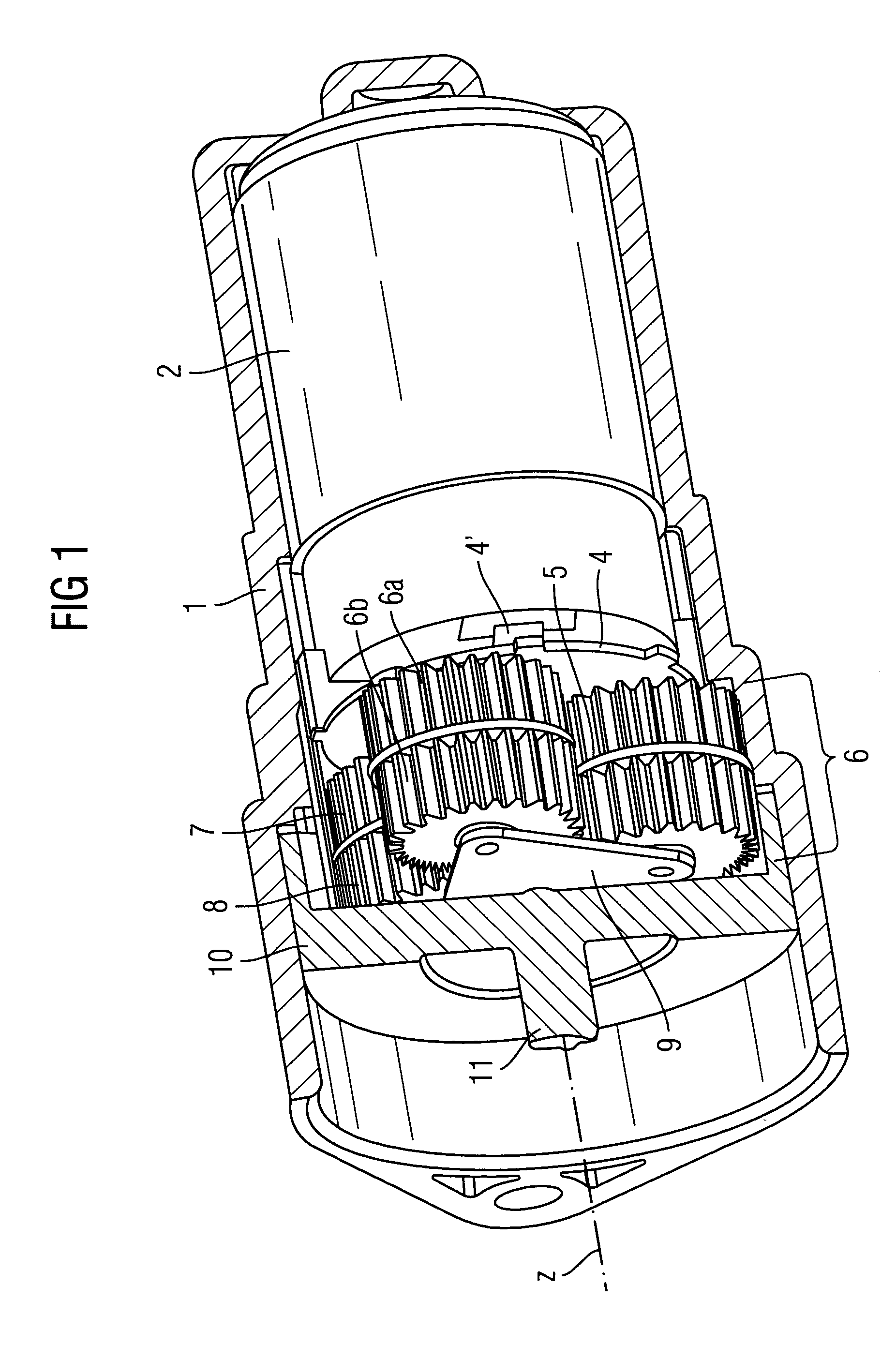
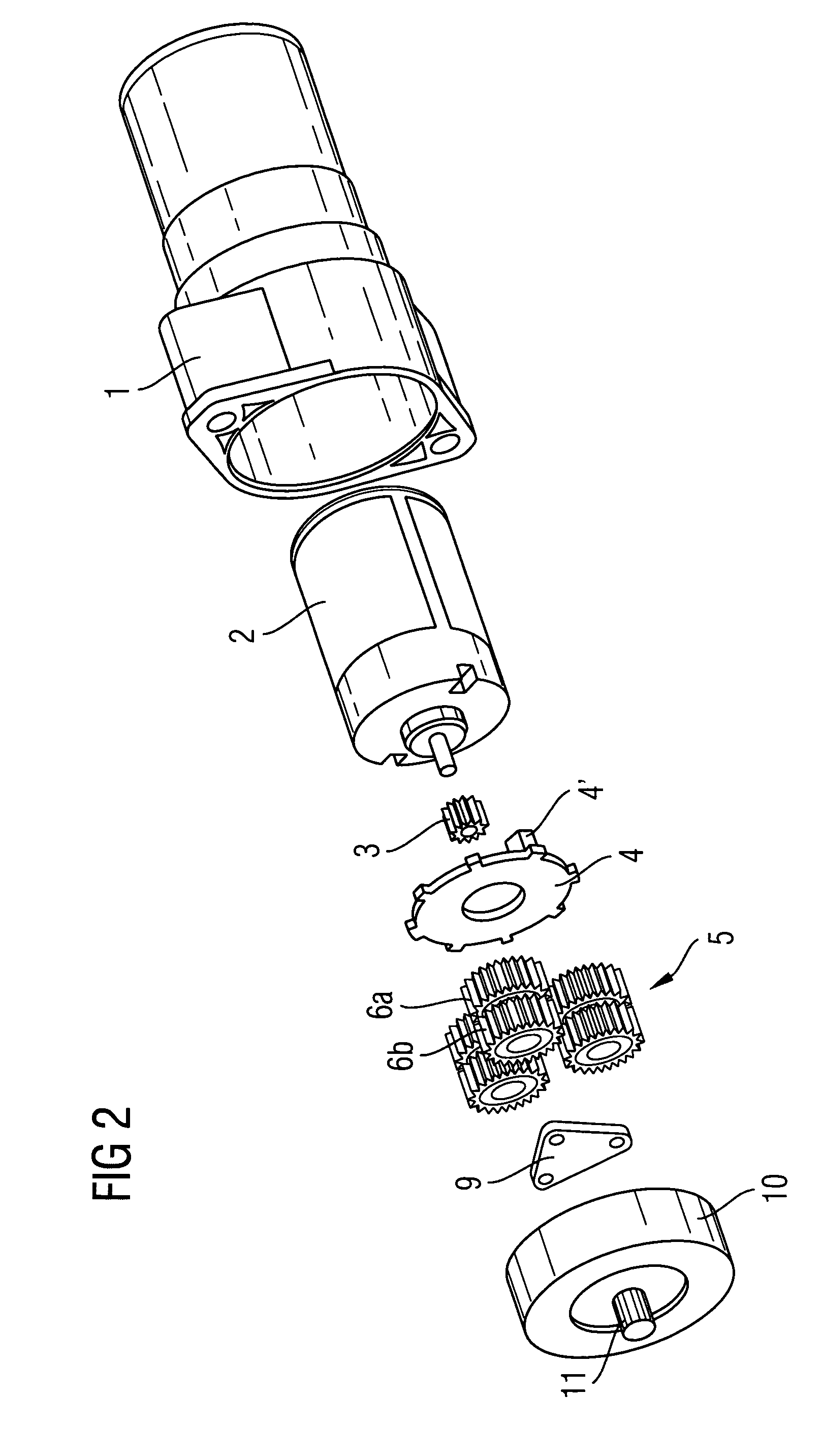
[0017]FIG. 1 is a three-dimensional illustration in partial section of one design of the actuator. The actuator comprises a housing 1 which has a longitudinal axis Z and in which an electric motor 2 is arranged. The pinion (not illustrated) of the electric motor 2 is used in each case to engage in a first gearwheel 6a of a planetary gear 5, which gearwheel forms, in each case together with a second gearwheel 6b arranged directly adjacent, a uniform double gearwheel 6. In this case, the double gearwheel 6 may, for example, comprise an individual part. Overall, three double gearwheels 6 are arranged. The respective first gearwheels 6a run in a first toothed ring 7, which constitutes a unit directly with the housing 1. The housing 1 and the first toothed ring 7 are therefore manufactured as an individual part. The respective second gearwheels 6b run in a rotatably mounted, second toothed ring 8, which is part of a cup-shaped wheel 10 which has, in the center of its side facing away fro...


PUM


Abstract

The actuator comprises a housing which has a longitudinal axis Z and in which an electric motor having a pinion is arranged. The pinion is in engagement in each case with at least one first gearwheel of a planetary gear, the first gearwheel forming, in each case together with a second gearwheel arranged directly adjacent, a uniform double gearwheel. One or more double gearwheels are arranged here. The first gearwheels run in a first toothed ring, which is connected fixedly to the housing. The respective second gearwheels run in a rotatably mounted, second toothed ring, which is connected to the part which is to be driven, with the number of teeth of the first toothed ring not being identical to the number of teeth of the second toothed ring. The invention furthermore relates to the use of the actuator for actuating a parking brake in a motor vehicle.

Description

BACKGROUND OF THE INVENTION [0001] The invention is concerned with an actuator and with a use of the actuator. Actuators are known. DE 199 34 161 C2 describes a swashplate mechanism having a shaft mounted in its housing. The gear function is based here essentially on pivoting an axis of a disk, which axis is set at an acute angle with respect to the drive shaft and output shaft, along a lateral area of a cone, so that it executes a wobbling or precision movement. In this case, the swash plate is secured rotatably by means of a double rolling bearing on a hollow cylinder, the axis of which is at the abovementioned, acute-angled inclination with respect to the axis of the supporting drive shaft, on which a hollow cylinder is, for its part, arranged in a rotationally fixed manner. Actuators of this type serve essentially to realize relatively high step-down ratios. A disadvantage of the device described in DE 199 34 161 C2 is that a relatively large structural space has to be provided ...

Claims


Application Information

Patent Timeline
Patent Type & Authority Applications(United States)
IPC IPC(8): F16H1/46H02K7/116
CPCF16H1/46Y10T74/19074H02K7/116F16H2001/2881
Inventor BAUKHOLT, THEOEMMEL, LARSFRANZ, ERHARDPFEIFFER, STEFANRIGORTH, MARCEL
Owner SIEMENS AG
Why Eureka
Try Eureka