Refractive focusing element for spectroscopic ellipsometry

a focusing element and spectroscopic technology, applied in the field of spectroscopy ellipsometry, can solve the problems of chromatic aberration of lenses, difficult to find lens materials with good transmission characteristics across a broad wavelength range, and the inability to focus broadband probe beams using lenses (refractive optics) to achieve the effect of focusing broadband probe beams

Inactive Publication Date: 2005-03-03
THERMA WAVE INC
View PDF11 Cites 7 Cited by
  • Summary
  • Abstract
  • Description
  • Claims
  • Application Information

AI Technical Summary

Benefits of technology

[0012] By using an all-refractive optical system for focusing the beam on the sample, problems associated with the alignment of mirrors are e

Problems solved by technology

Attempts to use lenses (refractive optics) to focus broadband probe beams, and particularly those including UV wavelengths, have run into problems.
First, lenses typically have chromatic aberrations.
Another problem with lenses is that it was often difficult to find lens materials with good transmission characteristics across a broad wavelength range.
Unfortunately, while providing a solution for chromatic aberration, mirrors are relatively difficult to align.
More specifically, since mirrors must be focus

Method used


Image

  • Refractive focusing element for spectroscopic ellipsometry
  • Refractive focusing element for spectroscopic ellipsometry
  • Refractive focusing element for spectroscopic ellipsometry

Examples


Embodiment Construction

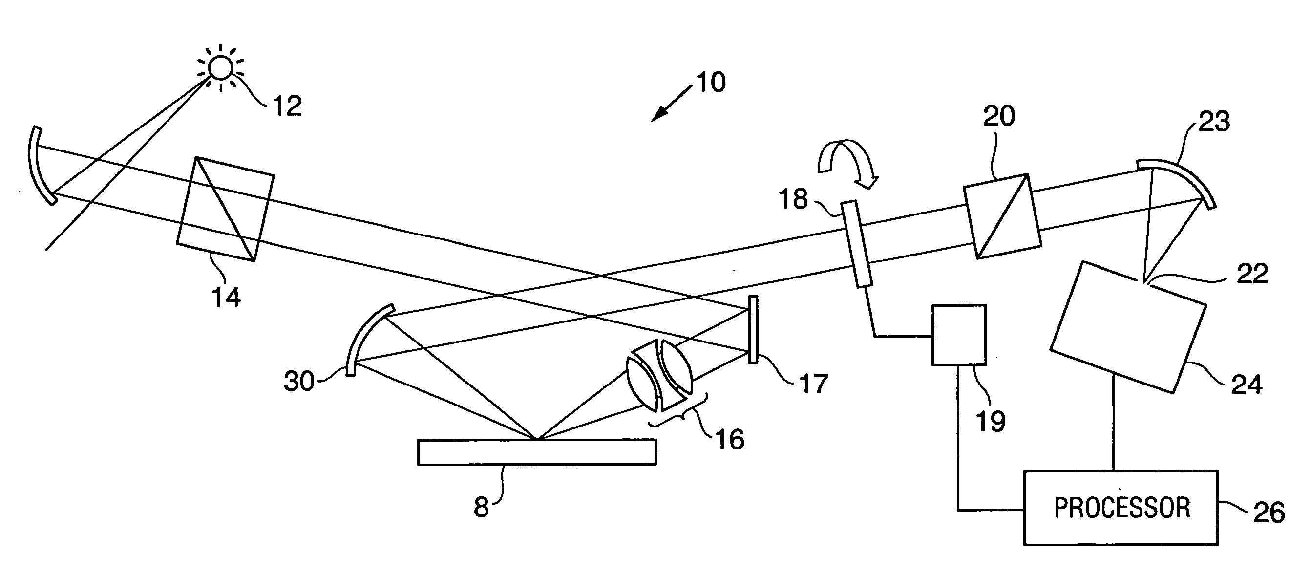
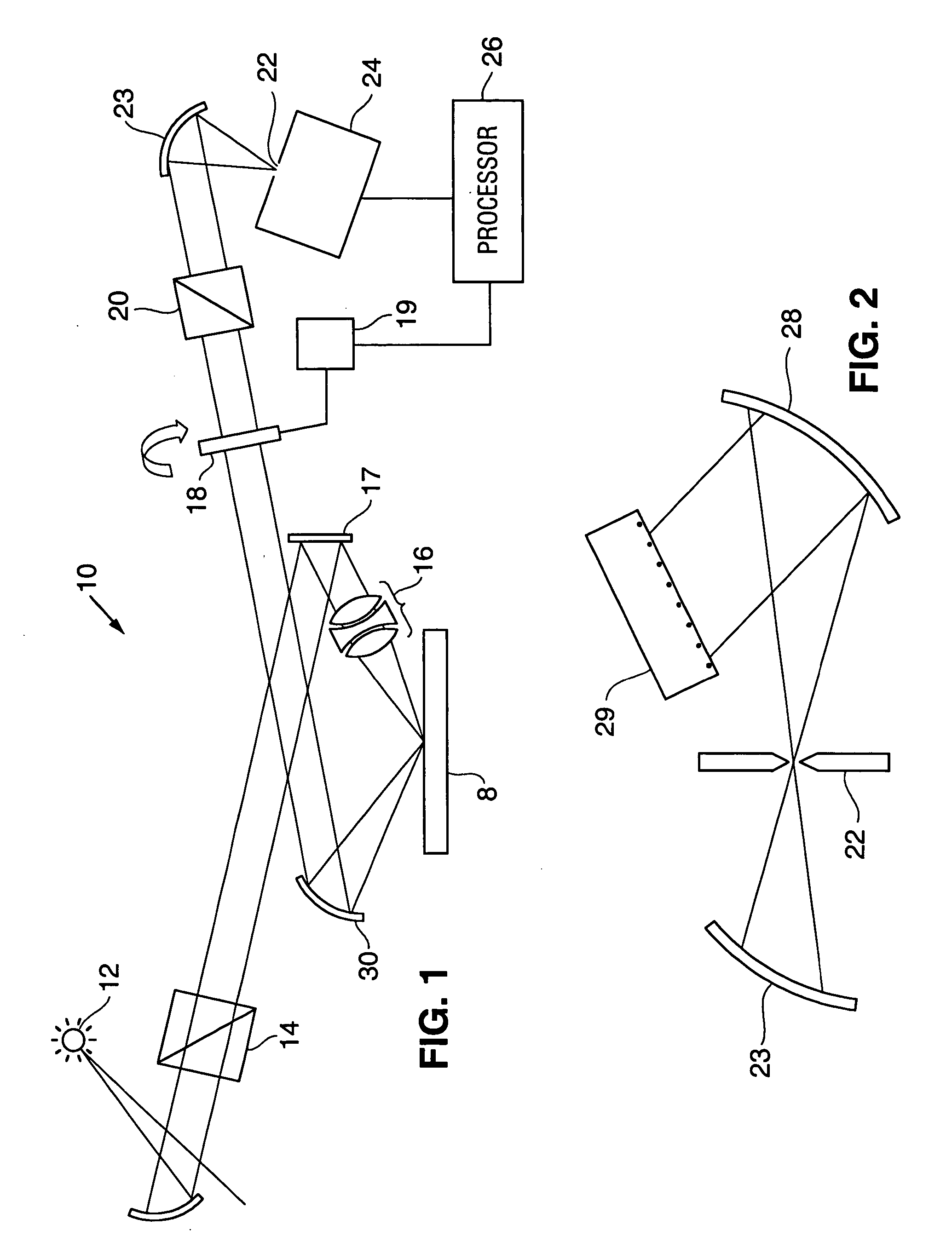
[0018] Referring to FIG. 1, a broadband ellipsometer 10 formed in accordance with the subject invention is illustrated. The ellipsometer includes a light source 12 for generating a polychromatic beam having both UV and visible wavelengths. This light source can be defined by a single lamp, or by two lamps such as a tungsten halogen for the visible range and a deuterium lamp for the UV wavelengths. The source would typically have a range of at least 500 nm and preferably covers a range from about 200 nm to 800 nm.

[0019] In the preferred embodiment, the light is directed through a polarizer 14 for establishing a fixed, known polarization of the light. The light is then directed into the all-refractive lens system 16 of the subject invention, either directly or via one or more turning mirrors 17. These turning mirrors would be essentially planar (flat), rather than curved. The lens system 16 focuses the light on the sample 8.

[0020] The light reflected from the sample is collimated by...


PUM


Abstract

A broadband ellipsometer is disclosed with an all-refractive optical system for focusing a probe beam on a sample. The ellipsometer includes a broadband light source emitting wavelengths in the UV and visible regions of the spectrum. The change in polarization state of the light reflected from the sample is arranged to evaluate characteristics of a sample. The probe beam is focused onto the sample using a composite lens system formed from materials transmissive in the UV and visible wavelengths and arranged to minimize chromatic aberrations. The spot size on the sample can be less than 3 mm and the aberration is such that the focal shift over the range of wavelengths is less than five percent of the mean focal length of the system.

Description

CLAIM OF PRIORITY [0001] This application is a continuation of U.S. patent application Ser. No. 09 / 848,733, filed May 3, 2001, entitled “SMALL SPOT SPECTROSCOPIC ELLIPSOMETER WITH REFRACTIVE FOCUSING,” which claims priority from prior provisional application Ser. No. 60 / 204,253 filed May 15, 2000, each of which is hereby incorporated herein by reference.TECHNICAL FIELD OF THE INVENTION [0002] The subject invention relates to spectroscopy ellipsometry. More specifically, the subject invention relates to an ellipsometer which utilizes an all-refractive optics system for focusing a broadband probe beam onto a sample. BACKGROUND [0003] Ellipsometry is a powerful technique for evaluating thin films on semiconductors. In any ellipsometer, a probe beam having a known polarization state is directed to interact with a sample. Changes in the polarization state induced by the interaction of the probe beam with the sample are then monitored. This information, in the form of Ψ and Δ measurements...

Claims


Application Information

Patent Timeline
IPC IPC(8): G01N21/21G02B1/02G02B7/02G02B13/14
CPCG01N21/211G01N2021/213G02B13/143G02B7/026G02B1/02
Inventor UHRICH, CRAIGCHEN, JIANHUI
Owner THERMA WAVE INC
Why Eureka
Try Eureka