Measuring apparatus

a technology of measuring apparatus and measuring chamber, which is applied in the direction of instruments, heat measurement, thermometer details, etc., can solve the problems of still remaining a measuring error, difficult to finely control the temperature of the atmosphere of the measuring apparatus, and control the temperature of the sensor unit itsel

a technology of measuring apparatus and measuring chamber, which is applied in the direction of instruments, heat measurement, thermometer details, etc., can solve the problems of still remaining a measuring error, difficult to finely control the temperature of the atmosphere of the measuring apparatus, and control the temperature of the sensor unit itsel

US20050046853A1Inactive Publication Date: 2005-03-03FUJIFILM HLDG CORP +1

Image

  • Measuring apparatus
  • Measuring apparatus
  • Measuring apparatus

Examples


Embodiment Construction

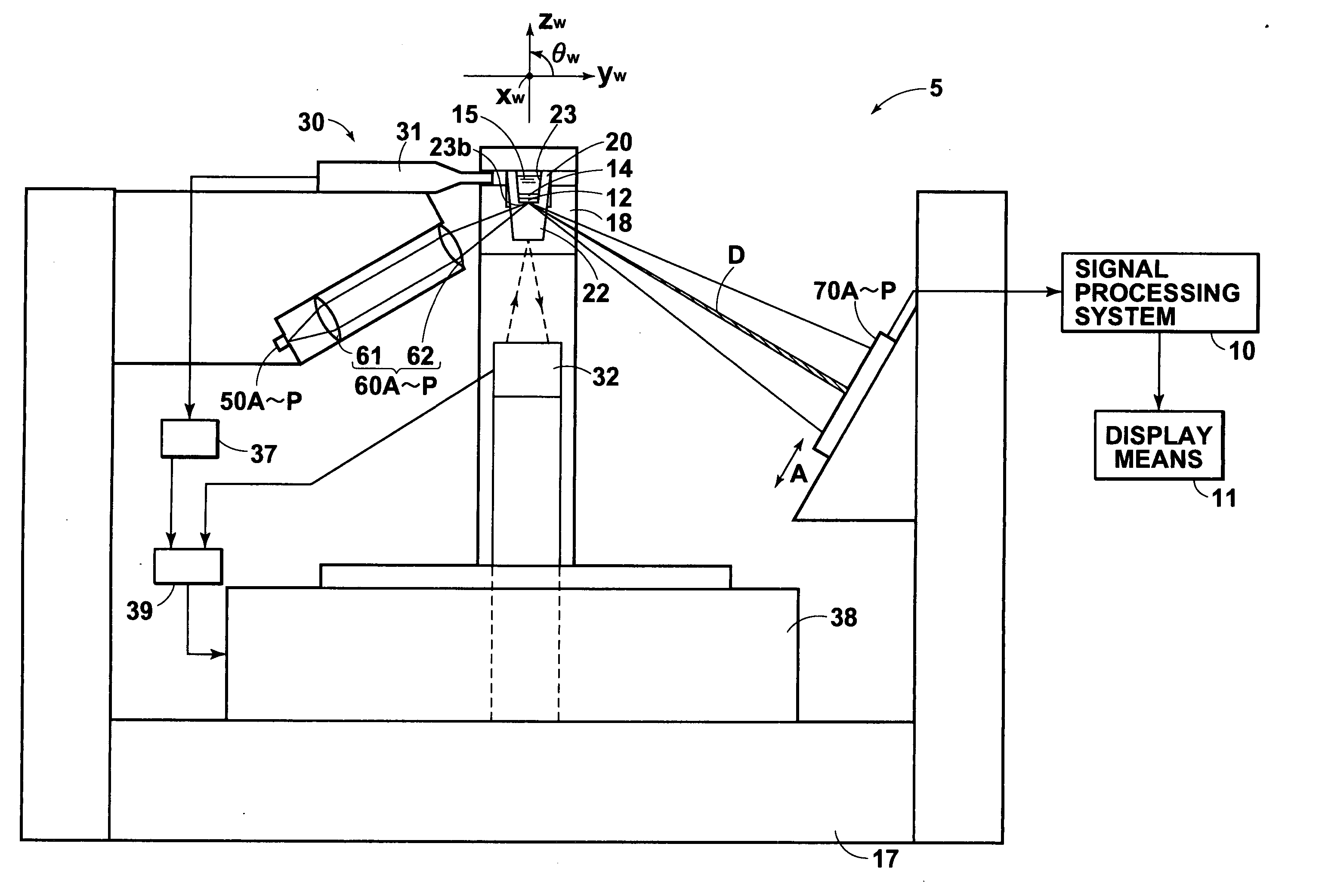
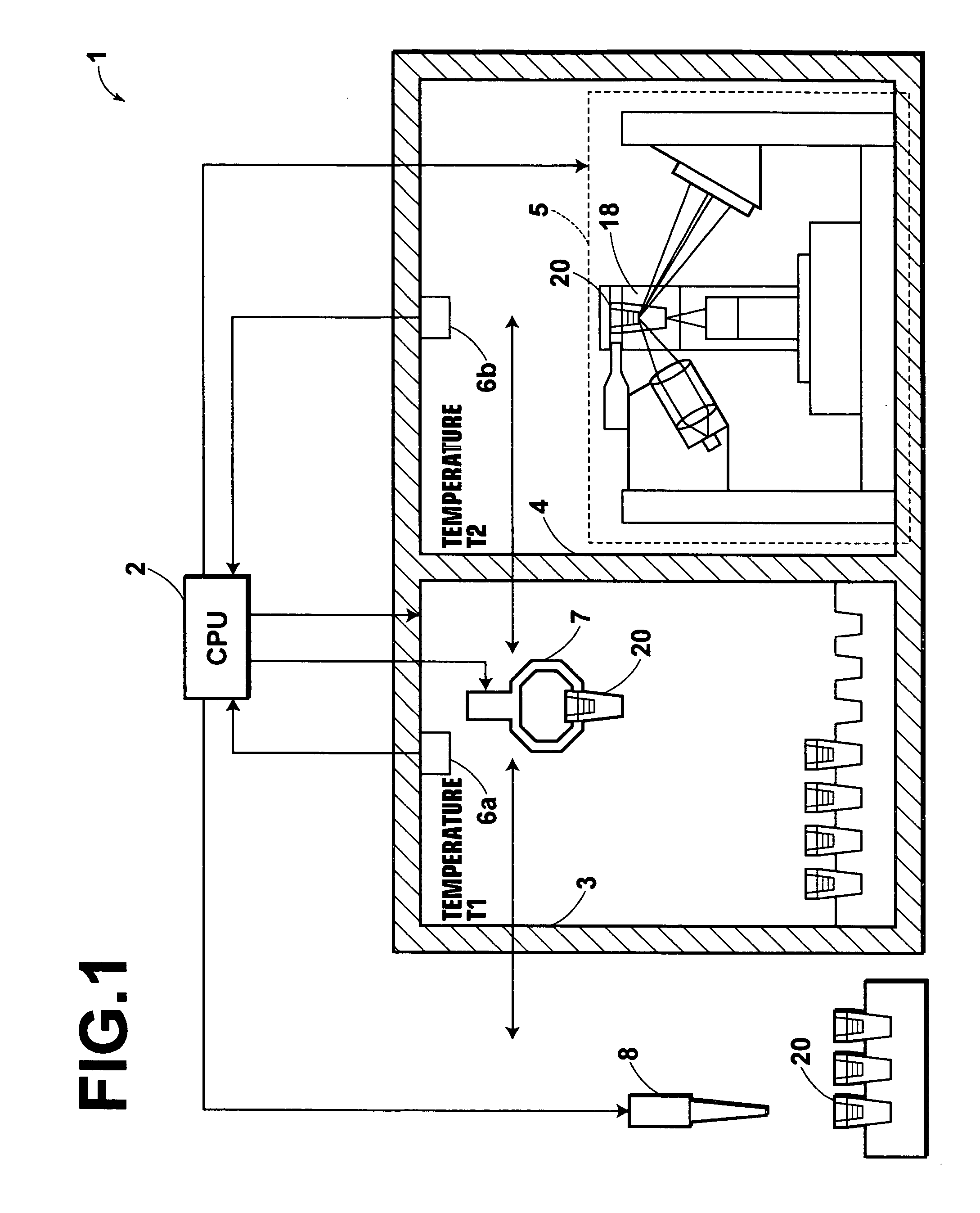
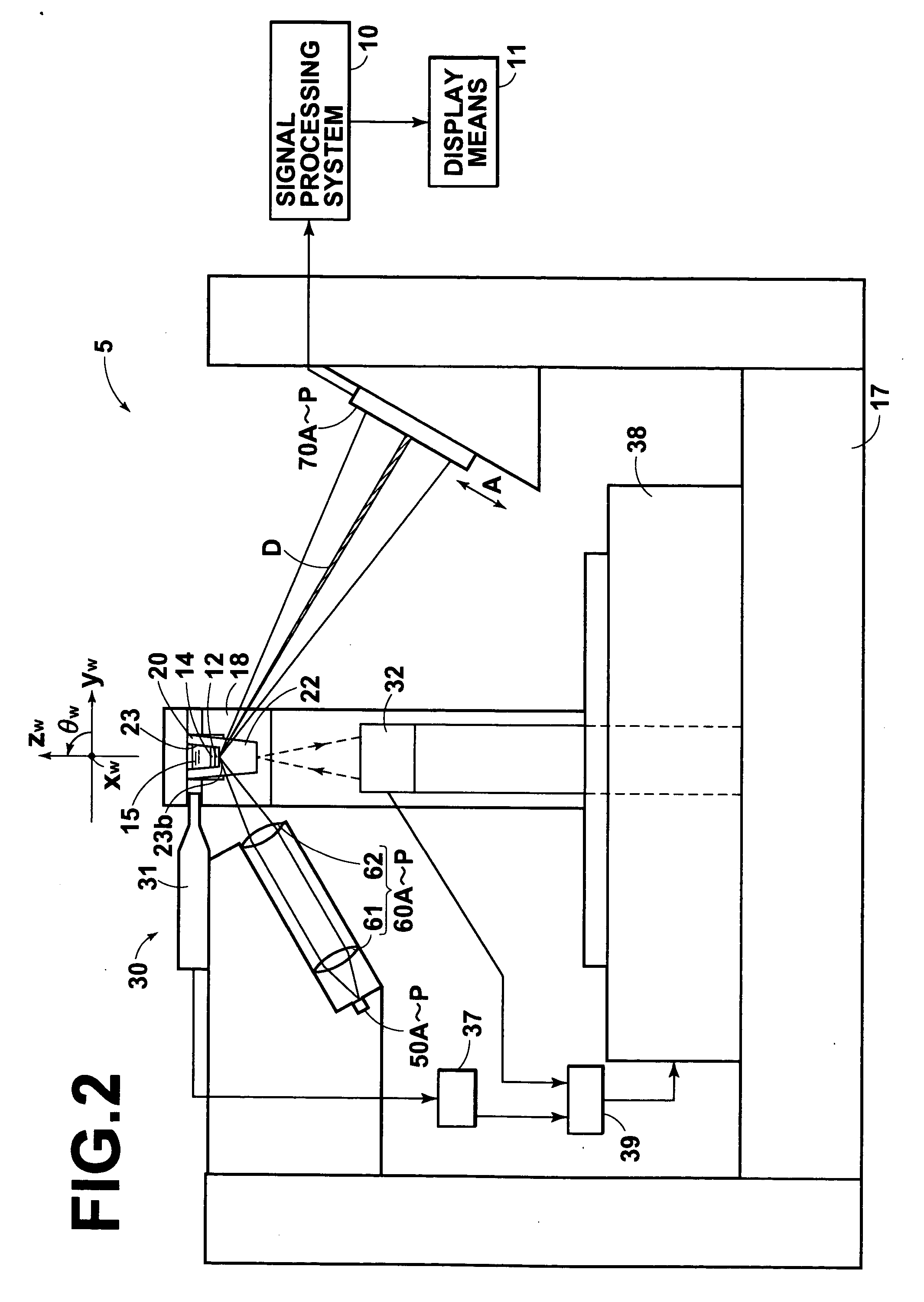
In FIG. 1, a measuring apparatus 1 in accordance with a first embodiment of the present invention comprises a sensor unit 20 to which a sample is dispensed, a surface plasmon resonance sensor 5 which analyzes the sample dispensed to the sensor unit 20, a measuring system 4 which accommodates the measuring means (the surface plasmon resonance sensor) 5, a constant temperature system 3 which is controlled to be at a predetermined temperature and stores the sensor unit 20, a temperature sensor 6a which measures the temperature of the measuring system, a temperature sensor 6b which measures the temperature of the measuring system 4, a conveyor means 7 which selectively positions the sensor unit 20 in a predetermined position in the measuring system 4 or in the constant temperature system 4, a dispenser 8 which dispenses the sample to the sensor unit 20, and a CPU (controlling means) 2 which controls the surface plasmon resonance sensor 5, the conveyor means 7 and the dispenser 8.

The ...


PUM


Abstract

In a surface plasmon resonance sensor, a sensor unit includes a dielectric block, a thin film layer which is formed on the upper surface of the dielectric block, and a sample holding portion. An incubator is provided, the surface plasmon resonance sensor is spatially isolated from the surroundings by placing it in the measuring system, the temperature of the measuring system is measured and temperature change of the sensor unit after it is conveyed to the measuring system from the incubator is estimated on the basis of the temperature difference between the temperature of the incubator and the temperature of the measuring system, and the sensor unit is conveyed to the measuring system to perform the measurement within a time for which the temperature of the sensor unit does not unacceptably change.

Description

BACKGROUND OF THE INVENTION 1. Field of the Invention This invention relates to a measuring apparatus such as a surface plasmon resonance sensor for analyzing a material in a sample on the basis of generation of surface plasmon. 2. Description of the Related Art In metal, free electrons vibrate in a group to generate compression waves called plasma waves. The compression waves generated in a metal surface are quantized as surface plasmon. There have been proposed various surface plasmon resonance sensors for quantitatively analyzing a material in a sample utilizing a phenomenon that such surface plasmon is excited by light waves. Among those, one employing a system called “Kretschmann configuration” is best known. See, for instance, Japanese Unexamined Patent Publication No. 6(1994)-167443. The surface plasmon resonance sensor using the Kretschmann configuration basically comprises a dielectric block shaped, for instance, like a prism, a metal film which is formed on one face ...

Claims


Application Information

Patent Timeline
03 Mar 2005
Publication
US20050046853A1
IPC
G01N21/01; G01N21/27; G01N21/41
CPC
G01N21/553
Inventors
SATO, SHU