

Interferometric modulator and display unit
a technology of interferometry and modulator, applied in the field of interferometry modulator and display unit, can solve the problems of chromatic aberration depending on the viewing angle, lower contrast of display methods, impracticality, etc., and achieve the effects of high brightness, high contrast ratio, and high reflectan
- Summary
- Abstract
- Description
- Claims
- Application Information
AI Technical Summary
Benefits of technology
Problems solved by technology
Method used
Image

Examples
first embodiment
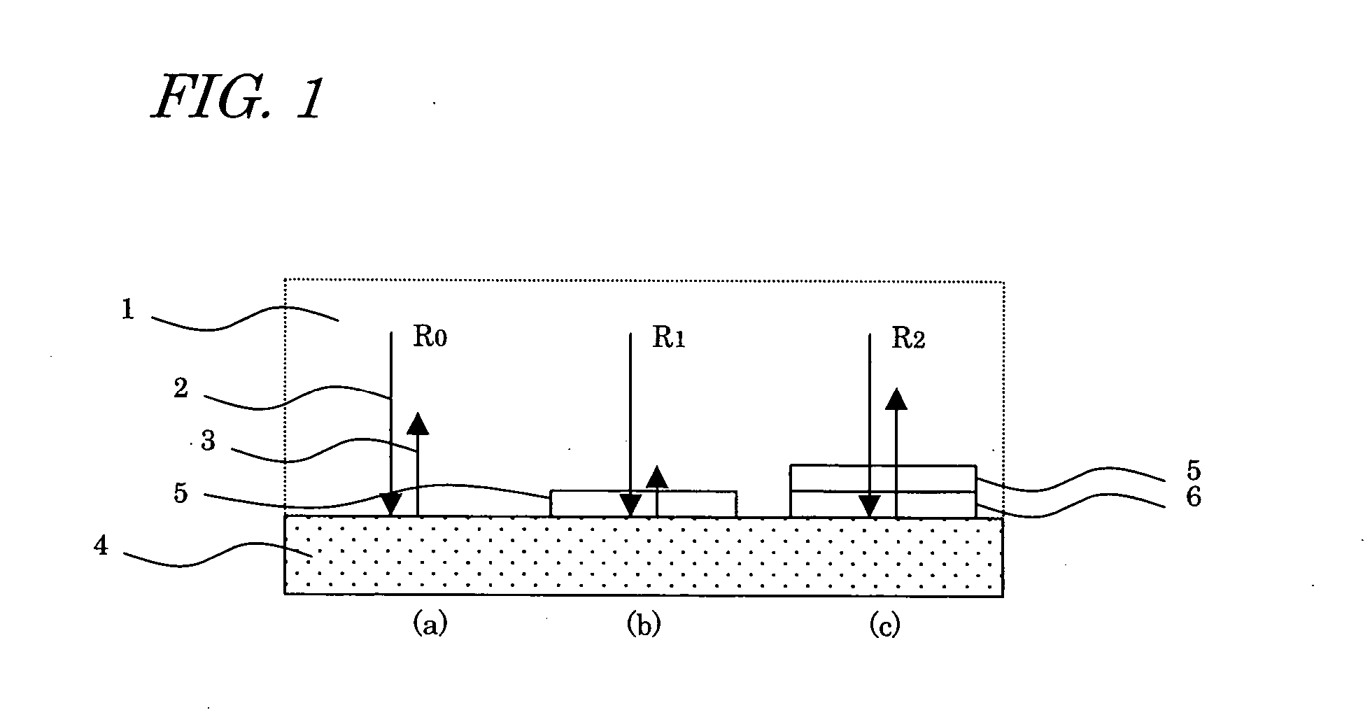
Referring to FIG. 1, the basic configuration and the operation principle of the interferometric modulator according to the invention will be firstly described.
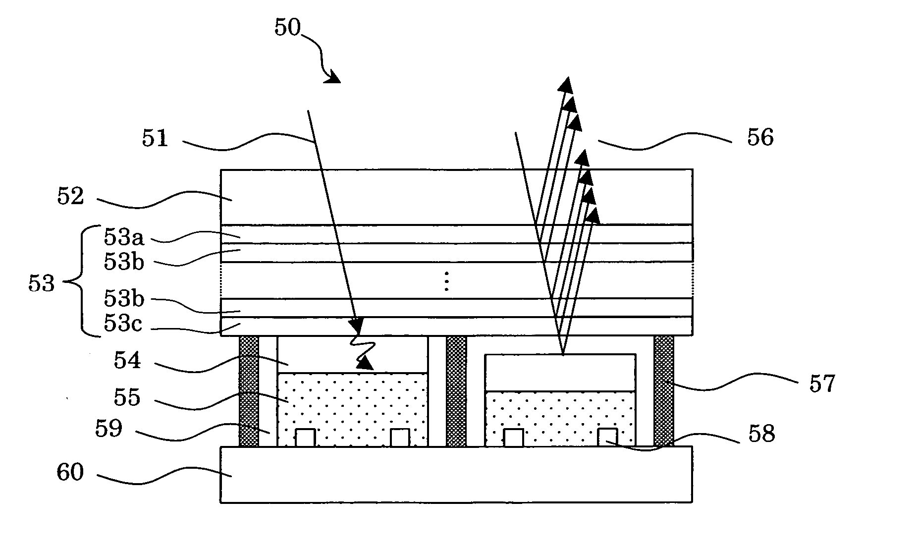
The interferometric modulator of the invention includes a transparent substrate (refractive index: n0), an optical thin film (complex index of refraction: N1=n1−i·k1) provided on the transparent substrate, and an absorber layer (complex index of refraction: Ns=ns−i·ks) opposed to the optical thin film, the distance of a gap to the optical thin film being variable, wherein the relation n1>n0, k1≅0 and ns>n0 is satisfied. This optical thin film acts to reduce (prevent) or increase the reflection in accordance with the distance of the gap to the absorber layer. For example, when the optical thin film is contacted with the absorber layer, it acts as a anti-reflection film, and when an air layer having a predetermined distance to the absorber layer is formed, it acts as a reflection enhancement film.
Generally, it is known that t...
embodiment 1
(Embodiment 1)
FIG. 3 is a schematic view showing the configuration of a reflection type display unit 10 according to a first embodiment of the invention. The reflection type display unit 10 has a plurality of interferometric modulators arranged like a matrix, in which each interferometric modulator constitutes a pixel, for example. FIG. 3 shows two pixels of the reflection type display unit, namely, two interferometric modulators, in which the left interferometric modulator is in a black display state (a state with the smallest reflectance) and the right interferometric modulator is in a white display state (a state with the largest reflectance).
Each of the interferometric modulators making up the reflection type display unit 10 includes a transparent substrate 12, an optical thin film 13 provided on the transparent substrate 12, and an absorber layer 14 having the variable distance of a gap to the optical thin film 13.
The absorber layer 14 is formed on a driving element 15 prov...
embodiment 2
(Embodiment 2)
FIG. 7 is a schematic view showing the configuration of a reflection type display unit 30 according to an embodiment 2 of the first aspect of the invention.
Each of the interferometric modulators making up the reflection type display unit 30 includes a transparent substrate 32, an optical thin film 33 provided on the transparent substrate 32, and an absorber layer 34 having the variable distance of a gap to the optical thin film 33.
The absorber layer 34 is formed on a driving element 35 provided on a substrate 40. The substrate 40 and the transparent substrate 32 (herein the optical thin film 33 formed on the transparent substrate 32) are spaced at a predetermined interval and fixed by the spacer walls 37. The spacer walls 37 enclose a medium 39 filling a gap formed between the absorber layer 34 and the optical thin film 33. The piezoelectric element 35 is controlled by one pair of electrodes 38.
When the absorber layer 34 and the optical thin film 33 are contacted...
PUM
 Abstract
Description
Claims
Application Information