Modem with pilot symbol synchronization

a modem and pilot symbol technology, applied in the direction of synchronisation transmitters, synchronisation signal speed/phase control, baseband system details, etc., can solve the problems of data quality degradation, and achieve the effect of less noise, faster determination, and more reliabl

Inactive Publication Date: 2005-03-03
L 3 COMM CORP
View PDF9 Cites 60 Cited by
  • Summary
  • Abstract
  • Description
  • Claims
  • Application Information

AI Technical Summary

Benefits of technology

[0009] In a typical construction of the transmission section of a communication system, digitized data, obtained from a source of data, is encoded by a suitable forward error correction code and then applied to a constellation mapper that provides any one of well known mappings for modulations such as BPSK, QPSK, QAM and FSK, by way of example. The data source, by way of example, may be a computer outputting digitized data, or speech-processing circuitry that converts voice into a digitized signal. A sequence of pilot symbols constituting a pilot word is stored in a memory of the transmission section, and the pilot word is also outputted to a constellation mapper providing one of the foregoing modulations. The modulated data and the modulated pilot symbols are multiplexed together to provide output sequences of pilot symbols interposed among sequences of data symbols. Thus, the multiplexing takes place after the pilot symbols and the data symbols are separately modulated. Therefore, an interleaving of sequences of pilot symbols with sequences of data symbols does not interfere with the formatting and modulation of the data signals. Thus, the present invention can be employed without derogating from the usual performance of the communication system.
[0010] At the receiver, the sequence of the pilot symbols is detected, as by use of a matched filter or a correlation process employing a replica of the sequence of the pilot symbols. In the practice of the invention, the length of the sequence of pilot symbols affects acquisition time such that a longer sequence provides for a faster determination of carrier phase, symbol timing and block or frame timing. The resulting estimates of carrier phase, symbol timing and block or frame timing are less noisy and more reliable. An increase in the length of the sequence of pilot symbols may detract from the amount of space available for sequences of data symbols so that, in practice, a trade-off may be necessary. In particular, the timing accuracy provided by the sequence of pilot symbols is sufficient for determining unambiguous carrier phase, symbol timing, block timing, and other parameters of the data transmission. The pilot symbol may also include codes or information useful for resetting a receiver, if desired. By way of example, this may include informing a receiver of switching data rate or modulation type. Thus, the invention rapidly and reliably establishes a time base with carrier phase and timing synchronization useful for equalization filter training, modem configuration switching, and turbo code synchronization, by way of example.

Problems solved by technology

This would present a problem if the data modulation is employed also for modulation of pilot symbols because the receiver might not be able to locate the pilot symbols due to the changing modulation.
This presents a problem in the case of a noisy communication link because the precise location, in time, of the synchronization pulse may be difficult to ascertain with a resulting degradation in the quality of reception of the data.

Method used


Image

  • Modem with pilot symbol synchronization
  • Modem with pilot symbol synchronization
  • Modem with pilot symbol synchronization

Examples


Embodiment Construction

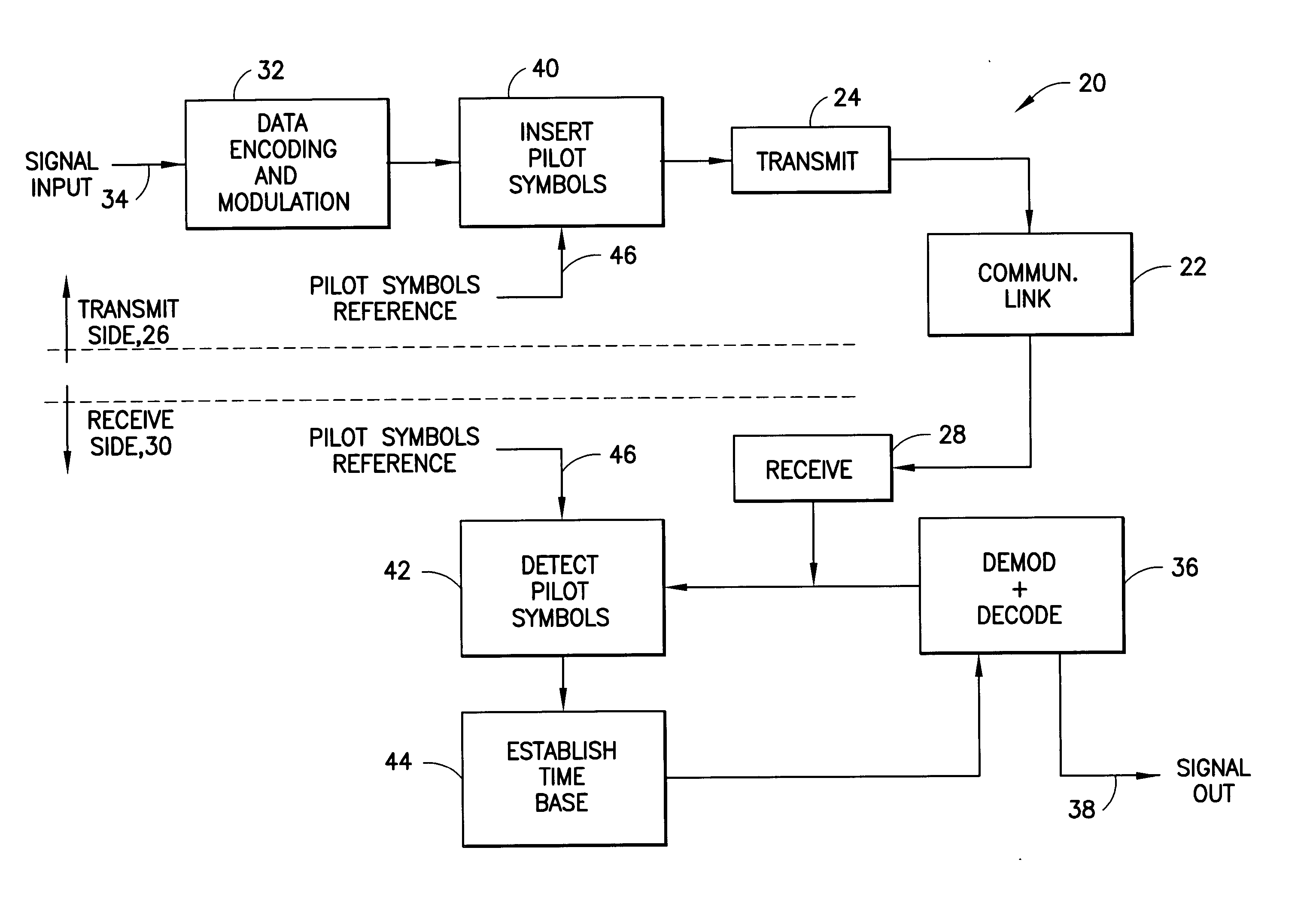
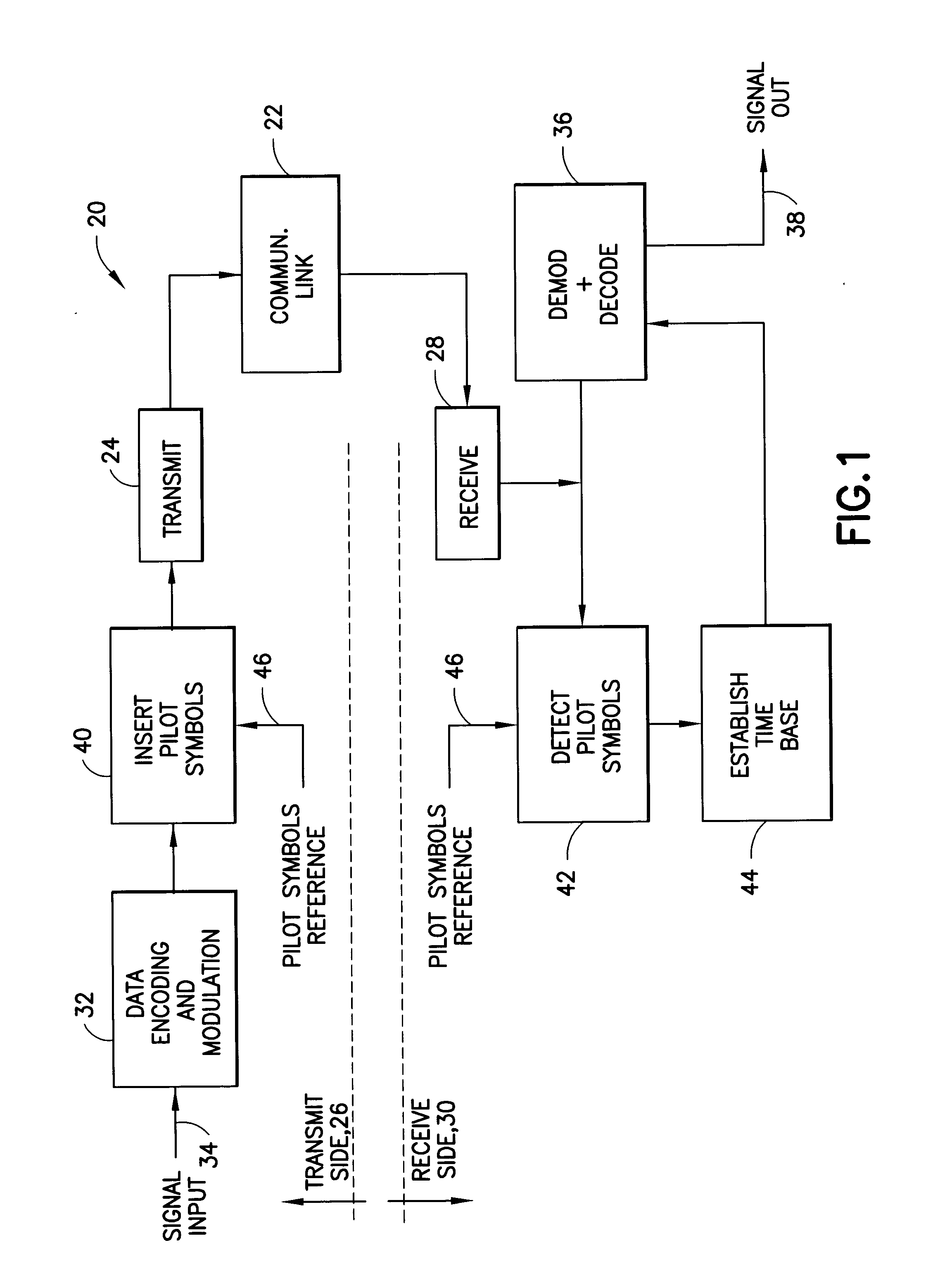
[0018] With reference to FIG. 1, a communication system 20 includes a communication link 22 connecting a transmitter 24, on a transmit side 26 of the link 22, with a receiver 28 on a receive side 30 of the link 22. Also included on the transmit side 26 is formatting circuitry 32, which includes coding circuitry (not shown in FIG. 1), for encoding and formatting an input signal, applied at an input terminal 34, as well as modulation circuitry (not shown in FIG. 1). The modulation circuitry and the encoding circuitry provides for a variety of signaling formats such as, by way of example, CDMA, TDMA, PSK, QAM, Reed Solomon coding, convolutional encoding and Turbo coding. More specifically, such circuitry provides data processing or formatting for error correction and phase ambiguity resolution for multiuser (TDMA, FDMA and CDMA), spread spectrum by direct sequence (DS) or frequency hopped (FH), and modulation / signaling (PSK, QAM, MSK). The formatting circuitry 32 may comprise a set of ...


PUM


Abstract

A modem, or a communication system, in its transmission section, has signal-formatting circuitry followed by circuitry for insertion of a sequence of pilot symbols into a sequence of data symbols outputted by the formatting circuitry. Placement of the insertion circuitry after the formatting circuitry permits a variety of formatting options without effecting the sequence of pilot symbols that serves as a time reference useful in detection of a signal transmitted by the modem. The reception section of the modem is equipped correspondingly to process a received composite signal of data symbols having a prescribed format and a sequence of pilot symbols. The reception section extracts the sequence of pilot symbols from the composite signal, and employs the pilot symbols to develop a time base for operation of circuitry for decoding the format of the received composite signal to extract data from the composite signal.

Description

BACKGROUND OF THE INVENTION [0001] 1. Field of the Invention [0002] This invention relates to a construction of a modem employing an inserted pilot symbol(s) for improved synchronization and equalization of demodulation circuitry within the modem and, more particularly, to the insertion of pilot symbols at a location within the transmitted symbol stream permitting use of the pilot symbols independently of the type of modulation applied to payload data. [0003] 2. Brief Description of Related Developments [0004] Communication systems are widely used in many situations including communication between persons, as in cellular telephony, and between various forms of equipment, such as between a satellite and a ground station. Various data formats and protocols have evolved to facilitate communication in differing situations. Communication may involve multiple access technologies such as CDMA (code division multiple access), TDMA (time division multiple access), FDMA (frequency division mu...

Claims


Application Information

Patent Timeline
Patent Type & Authority Applications(United States)
IPC IPC(8): H04L7/00H04L7/04H04L25/03
CPCH04L7/0091H04L2025/03796H04L2025/03375H04L7/042
Inventor MCINTIRE, WILLIAM K.FONNESBECK, DALE D.HADDADIN, OSAMA S.
Owner L 3 COMM CORP
Why Eureka
Try Eureka