Automated laminate inspection method

Inactive Publication Date: 2005-03-03
LOWE ELVIN P
View PDF11 Cites 29 Cited by
  • Summary
  • Abstract
  • Description
  • Claims
  • Application Information

AI Technical Summary

Benefits of technology

[0029] An advantage of the present invention is that it works instantly to analyze samples.
[0030] Another advantage of the present invention is that it uses recent pixel technology in scanners and cameras.
[0031] An additional advantage of the present invention is that it may be used in an automated manufacturing process.
[0032] One more

Problems solved by technology

Currently, quality control procedures utilize as fabricated product thickness and laboratory destructive testing of a specimen from the end product.
This methodology does not verify the precise thickness or the reinforcing fiber to matrix material ratio for each layer or ply within the cross section of the laminated end product.
Additionally, the time required to perform these test renders the results useless in real time control of the manufacturing process for end products.
There is no physical evidence available for future evaluation.
This process is labor intensive and time consuming.
Additionally, interpretat

Method used


Image

  • Automated laminate inspection method
  • Automated laminate inspection method

Examples


Embodiment Construction

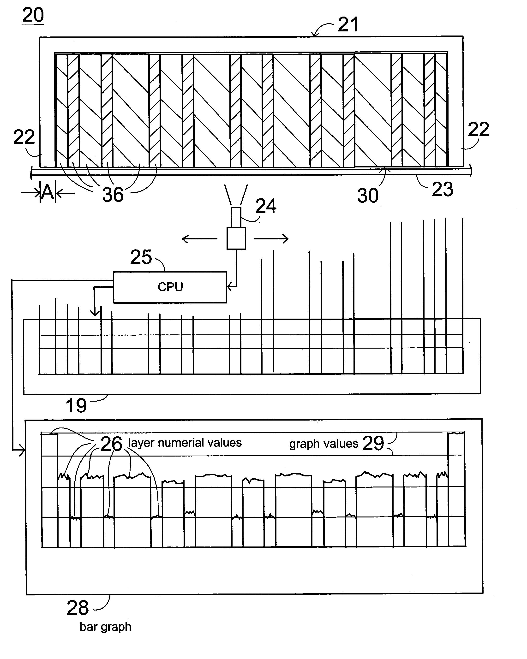
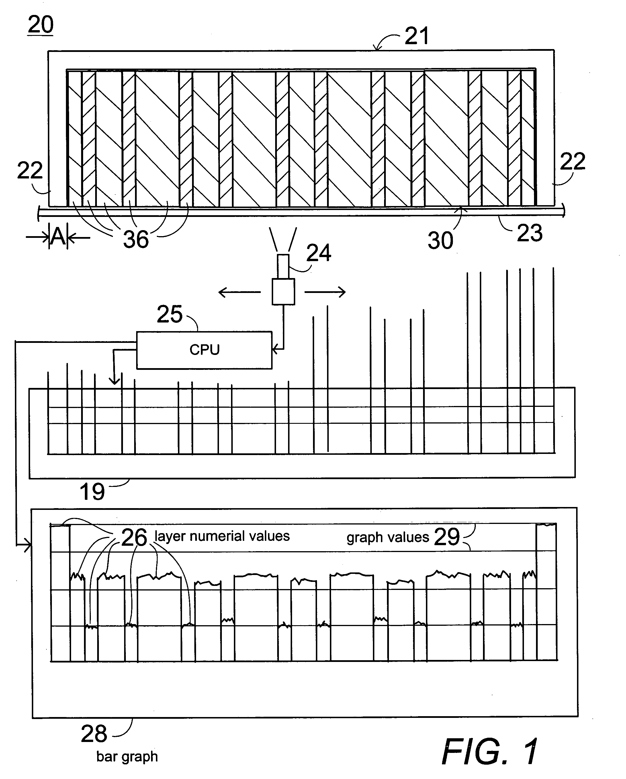
[0037] In FIG. 1, a system 20 is shown for determining characteristics of laminate material 30, including fiber composite laminate material, metal laminates, brazed parts, welded parts, sandwich parts to determine layer thickness and layer properties such as fiber content, matrix content, density, void content, and other desired properties related to quality control for real time feedback to manufacturing and archiving for future reference, in particular for the determination of the thickness of each ply, and of the physical properties and of the stacking order and the fiber orientation of a fiber reinforced laminate, and the thickness of each ply of metal and sandwich laminates as well as bonded, welded and brazed joints. The system 20 comprises a holder 21 that is capable of supporting a sample piece of laminate material 30 so that an edge of the sample piece of laminate material 30 reveals a clearly visible view of the laminated layers 36 of the material 30 which may comprise fib...


PUM

PropertyMeasurementUnit
Timeaaaaaaaaaa
Thicknessaaaaaaaaaa
Angleaaaaaaaaaa

Abstract

An optical scanner scans a piece support of know thickness holding a cross-section of laminate material such as fiber composite laminate, metal laminates, brazed parts, welded parts, sandwiched parts to determine layer thickness and layer properties such as fiber content, matrix content, density, void content, and other desired properties related to quality control for real time feedback to manufacturing and archiving for future reference. The electronic visual image from the scan depicts the number and quality of pixels in each layer. A programmable data processor uses the scan information and reference data to determine the physical properties and of the stacking order and the fiber orientation of a fiber reinforced laminate, and the thickness of each ply of metal and sandwich laminates as well as bonded, welded and brazed joints and for the determination of the thickness of each ply, of the stacking order and fiber orientation of a fiber reinforced laminate. The processor outputs real time data and a connected data storage memory archives the information for future reference.

Description

BACKGROUND OF THE INVENTION [0001] 1. Field of the Invention [0002] The present invention relates to a method and an apparatus for inspection of laminate material and in particular to the visual inspection by scanning for the characterization of laminate material, including fiber composite laminate material, metal laminates, brazed parts, welded parts, sandwich parts to determine layer thickness and layer properties such as fiber content, matrix content, density, void content, and other desired properties related to quality control for real time feedback to manufacturing and archiving for future reference, in particular for the determination of the thickness of each ply, and of the physical properties and of the stacking order and the fiber orientation of a fiber reinforced laminate, and the thickness of each ply of metal and sandwich laminates as well as bonded, welded and brazed joints. [0003] 2. Description of the Prior Art [0004] Laminated materials, due to the ability to tailor...

Claims


Application Information

Patent Timeline
IPC IPC(8): G01N21/88G06K9/00
CPCG01N21/8851G01N2021/8472Y10T428/24124Y10T428/24992Y10T156/1075
Inventor LOWE, ELVIN P.
Owner LOWE ELVIN P
Why Eureka
Try Eureka