Thin bond-line silicone adhesive composition and method for preparing the same
a silicone adhesive and composition technology, applied in the direction of special tyres, semiconductor/solid-state device details, transportation and packaging, etc., can solve the problems of reducing the effectiveness and value of the heat dissipating unit, reducing the ability to transfer heat through the interface between the surfaces, and not always achieving minimum bond lines. , to achieve the effect of low viscosity, low bond line thickness and reduced thermal resistan
- Summary
- Abstract
- Description
- Claims
- Application Information
AI Technical Summary
Benefits of technology
Problems solved by technology
Method used
Image
Examples
example 1
[0054] Two separate thermally conductive fillers were used in this formulation. The first filler was Filler C and the second filler was Filler D. These two fillers were used in a ratio of 4:1 by weight in this formulation. The thermally conductive fillers (604.29 parts total) were mixed in a lab scale Ross mixer (1 quart capacity) at approximately 18 rpm for 2.5 hours at 140-160° C. at a vacuum pressure of 25-30 inches Hg. The fillers were then cooled to 35-45° C., brought to atmospheric pressure, and 100 parts of vinyl-stopped polydimethylsiloxane fluid (350-450 cSt, approximately 0.48 weight percent vinyl) along with 0.71 parts of a pigment masterbatch (50 weight percent carbon black and 50 weight percent of a 10,000 cSt vinyl-stopped polydimethylsiloxane fluid) and a portion of the hydride fluid was added (0.66 parts of hydride functionalized polyorganosiloxane fluid, approximately 0.82 weight percent hydride). The formulation was mixed at approximately 18 rpm for 6 minutes to in...
example 2
[0060] The formulation and process of this Example followed that of Example 1, with the exception of the filler identity and composition. In this Example, only one filler type was used. Filler A, which had maximal particle sizes exceeding 25 microns, was used exclusively and represented 604.29 total parts of the formulation. The physical properties of this formulation were determined as described above in Example 1.
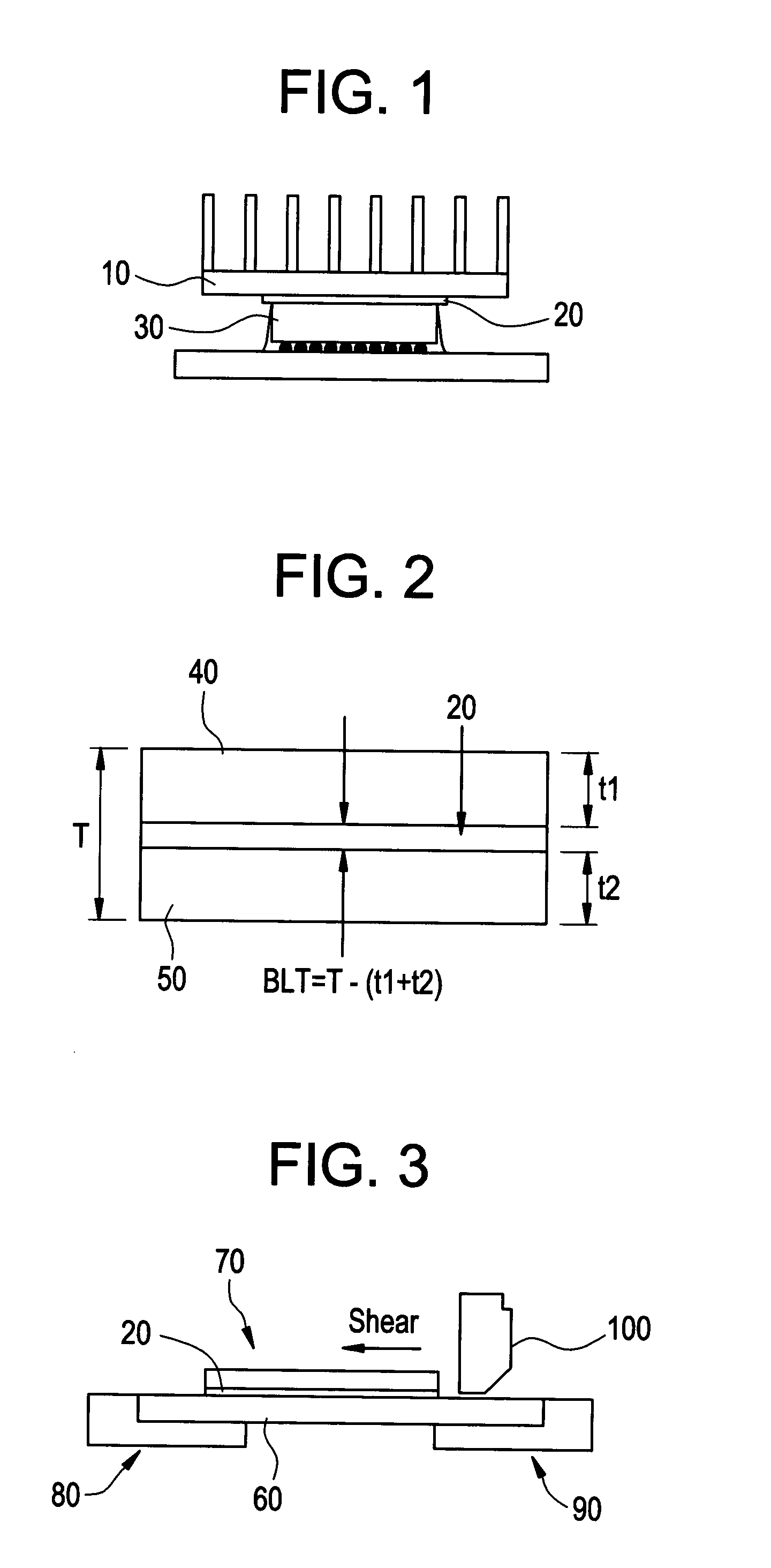
[0061] Formulations with optimal properties were prepared by controlling both the recipe and the mixing parameters. Table 2 below provides a summary of the physical properties for the formulations of Examples 1 and 2. As seen from Table 2, thermal interface materials prepared from Example 1 had a bond line thickness that was approximately 50% lower than those prepared from Example 2. The in-situ thermal resistance of TIM prepared from Example 1 was also about 40% lower than that prepared from Example 2.
TABLE 2Physical Properties of Examples 1-2Example12Physical Propert...
example 3
[0062] Two separate thermally conductive fillers were used in this formulation. The first filler was Filler C and the second filler was Filler D. These two fillers were used in a ratio of 4:1 by weight in this formulation. The thermally conductive fillers (1,028.66 parts total) were mixed in a lab scale Ross mixer (1 quart capacity) at approximately 18 rpm for 2.5 hours at 140-160° C. at a vacuum pressure of 25-30 inches Hg. The fillers were then cooled to 35-45° C., brought to atmospheric pressure, and 100 parts of vinyl-stopped polydimethylsiloxane fluid (200-300 cSt, 0.53-0.71 weight percent vinyl) along with 1.16 parts of a pigment masterbatch (50 weight percent carbon black and 50 weight percent of a 10,000 cSt vinyl-stopped polydimethylsiloxane fluid) and a portion of each of the hydride fluids were added: 0.97 parts of hydride functionalized polyorganosiloxane fluid (0.72-1.0 weight percent hydride) and 5.73 parts of hydride stopped polydimethylsiloxane fluid (500-600 ppm hyd...
PUM
| Property | Measurement | Unit |
|---|---|---|
| Temperature | aaaaa | aaaaa |
| Temperature | aaaaa | aaaaa |
| Temperature | aaaaa | aaaaa |
Abstract
Description
Claims
Application Information
 - R&D
- Intellectual Property
- Life Sciences
- Materials
- Tech Scout
- Unparalleled Data Quality
- Higher Quality Content
- 60% Fewer Hallucinations
Browse by: Latest US Patents, China's latest patents, Technical Efficacy Thesaurus, Application Domain, Technology Topic, Popular Technical Reports.
© 2025 PatSnap. All rights reserved.Legal|Privacy policy|Modern Slavery Act Transparency Statement|Sitemap|About US| Contact US: help@patsnap.com

