Painting system

Active Publication Date: 2005-03-10
ABB (SCHWEIZ) AG
View PDF20 Cites 22 Cited by
  • Summary
  • Abstract
  • Description
  • Claims
  • Application Information

AI Technical Summary

Benefits of technology

[0008] A primary object of the present invention is to provide a paint system for large objects, which involves a lesser number of stationary painting robots, involving a smaller paint booth and which offers a higher production capacity per robot installed. A paint booth in this context is a sealed of environment comprising a floor, a ceiling and walls which have open

Problems solved by technology

Apparatus of this type may have a sufficient range of reciprocal motion in the vertical direction, but have rather limited ranges of motion in the transverse direction of the painting booth, and practically no option for tracking the object to be painted in the direction of the conveyor motion through the booth.
Track means comprising rails however are costly and very delicate in function on dirt and particles on the rails.
Thus it is difficult to keep track of the robot position on the rails.
The more manipulators inside th

Method used


Image

  • Painting system
  • Painting system
  • Painting system

Examples


Embodiment Construction

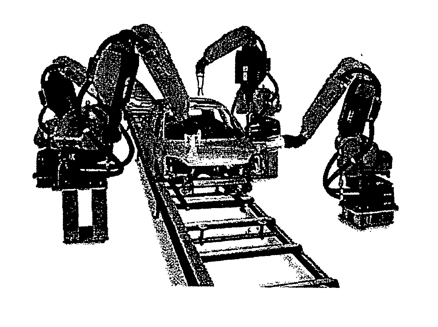
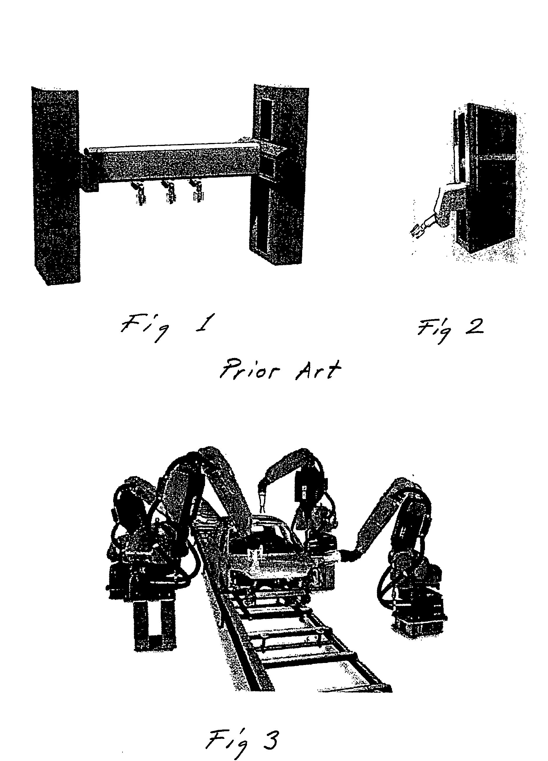
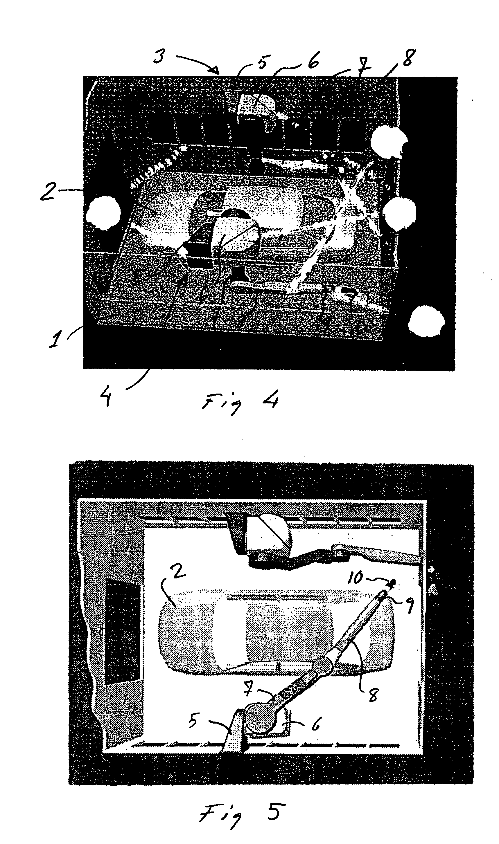
[0025] According to FIG. 4 a painting system according to the invention comprises a painting booth 1, in which is placed an object, a car body, 2 to be painted. The booth also comprises a first painting robot 3 and a second painting robot 3. Each of the painting robots comprises a base 5 attached to the wall of the booth. The base comprises a cantilever construction and carries a stand 6 rotatably arranged around a first axis, which in the embodiment shown is oriented in the direction of the length of the booth. The stand carries a first arm 7 rotatably arranged around a second axis, which in the embodiment shown is oriented normal to the first axis. The first arm carries a second arm 8 rotatably arranged around a third axis, which in the embodiment shown is oriented parallel to the second axis. The second arm carries an end effector comprising an arm part arrangement 9 with three degrees of freedom moveability. Finally the end effector arrangement caries a painting tool 10 in the f...


PUM


Abstract

Painting system for painting large objects comprising a paint booth with surrounding walls and a robot installation comprising a plurality of painting robots, each painting robot comprising a stationary base, a stand carried by the base rotatably arranged around a first axis, a first arm carried by the stand rotatably arranged around a second axis, a second arm carried by the first arm rotatably arranged around a third axis and a forth, a fifth and a sixth arm part carried by the second arm for orienting an attached painting tool.

Description

TECHNICAL FIELD [0001] This present invention concerns a painting system comprising a paint booth and a robot installation for painting large objects inside the painting booth. More precisely the invention concerns such a painting system including a paint booth with walls isolating the object to be painted from the surroundings. Especially the invention concerns such a system wherein the robot installation contains at least two industrial robots, each comprising at least four axes for servo-controlled movements. An industrial robot in this context comprises a manipulator with electric motors and a control means containing power means for driving the motors and computer means which by instructions from a computer program is arranged for sensing and controlling the manipulator movements BACKGROUND OF THE INVENTION [0002] Painting of car bodies on an industrial scale usually takes place in a painting booth, through which the car bodies are moved on a conveyor in a line succession. For ...

Claims


Application Information

Patent Timeline
IPC IPC(8): B25J9/06B05B1/28B05B12/00B05B13/04B05B15/12B05C5/00B05D1/02B25J9/00
CPCB05B13/0452B05B15/12B25J19/0079B25J9/0084B25J11/0075B05B13/0431B05B16/00
Inventor KROGEDAL, ARNULFBRYNE, GISLE
Owner ABB (SCHWEIZ) AG
Why Eureka
Try Eureka