

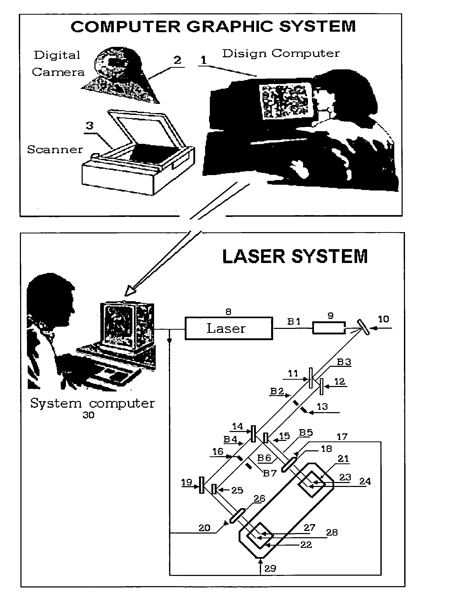
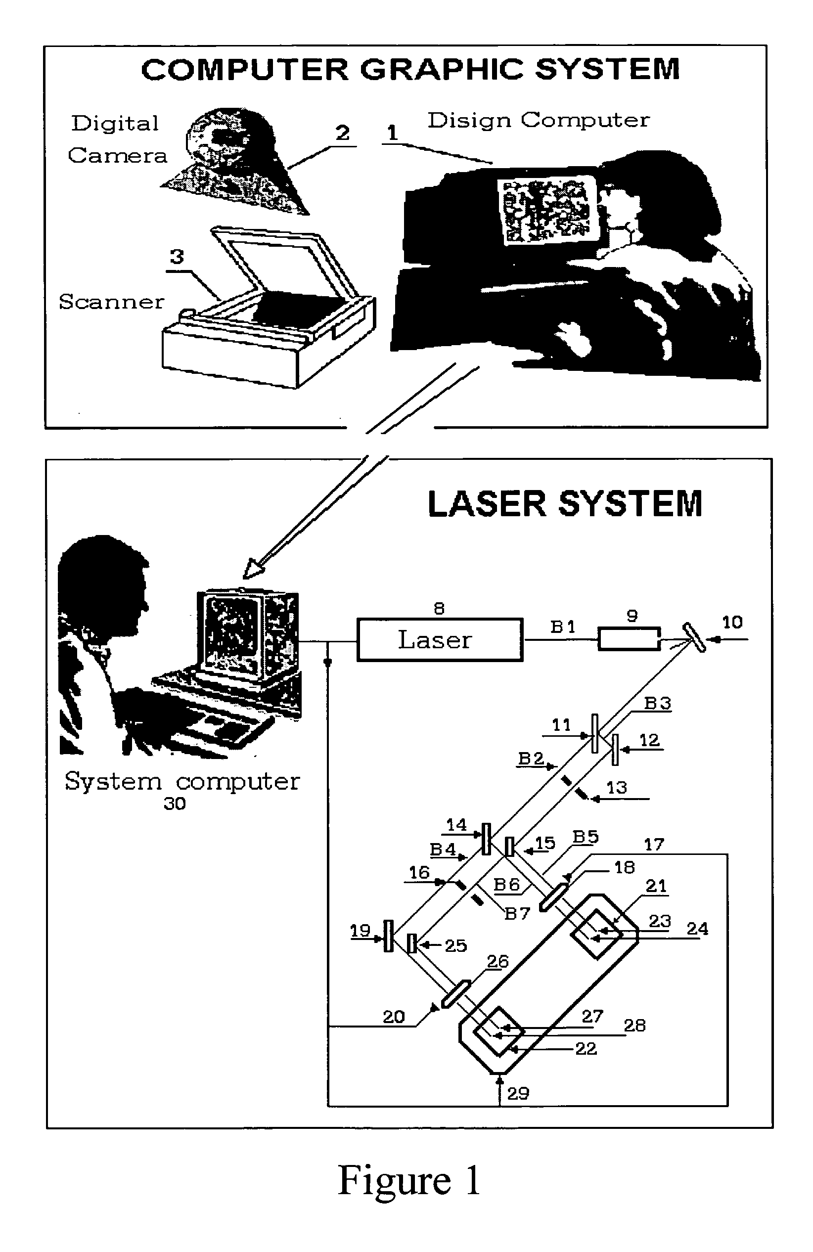
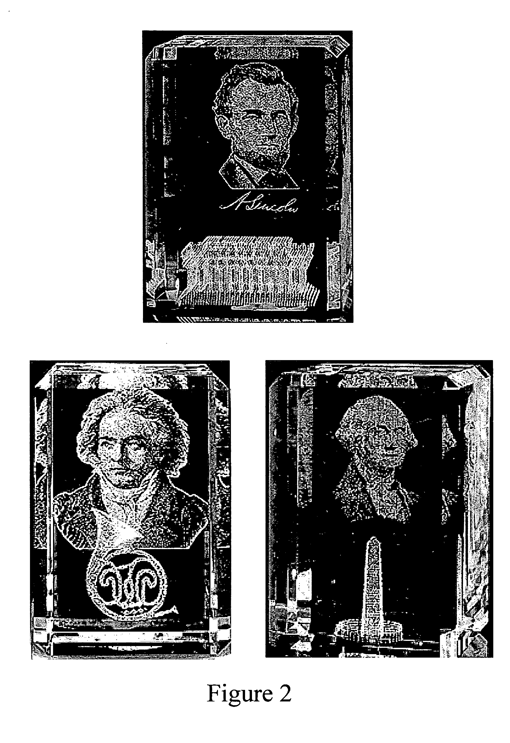
Laser-computer graphics system for generating portrait and 3-D sculpture reproductions inside optically transparent material
- Summary
- Abstract
- Description
- Claims
- Application Information
AI Technical Summary
Benefits of technology
Problems solved by technology
Method used
Image

Examples
first embodiment
the invention is based upon the physical phenomenon that if a viewer looks at etch points in the material where two or more etch points are aligned one after another and they are not far from each other, then the viewer sees their projection on visual plane (i.e. plane perpendicular to observation direction) as having a brightness greater than a single point. In other words, the greater number of points which are positioned in alignment, the higher the sum of the brightness of their projection. A first method of gray shade generation of the invention has the very important advantage of reducing gray shade fluctuation since the brightness of their projection comprises the average brightness of the separated points.
By way of illustration, FIG. 5(a) shows an etch point projection having a first brightness. FIG. 5(b) is a projection of two etch points following one after another, this projection having a greater brightness. FIG. 5(c) shows a plurality of different etch points. It can b...
second embodiment
the invention is based upon the physical phenomenon that when the dimensions of an etch point increase, its brightness increases. Different dimensions of etch points can be achieved in at least the following two ways: (1) the dimensions of an etch point increase when the laser radiation energy used to create the point increases; and (2) the dimensions of an etch point increase as the number of laser radiation pulses directed at the same point increases.
Another embodiment of a method of the present invention consists of the following steps: Step B1: This step is the same as step Al of the previous embodiment. Step B2: A number of one-shade gray images M are formed from the basic or original image. Unlike the previous method, these images are not identical to the basic image. Instead, a first one-shade image consists only of those areas of the basic image where the gray shade nearest to black is not equal to zero. The second one-shade image consists of only those areas where the se...
PUM
| Property | Measurement | Unit |
|---|---|---|
| Density | aaaaa | aaaaa |
| Transparency | aaaaa | aaaaa |
| Distance | aaaaa | aaaaa |
Abstract
Description
Claims
Application Information