Projecting system

Inactive Publication Date: 2005-03-10
VIVAVR TECH
View PDF2 Cites 54 Cited by
  • Summary
  • Abstract
  • Description
  • Claims
  • Application Information

AI Technical Summary

Benefits of technology

[0013] An objective of the invention is to provide a projecting system with flexibility and scalability that can be quickly set up. Another objective of the invention is to provide a playing system that uses a number of projectors to produce an image. A further objective of the invention is to provide a playing program for several projecto

Problems solved by technology

However, these screens are often limited by their sizes.
Once they reach a certain size, the cost increases quickly.
In other words, the screen is often distorted when the shape/size of the screen or the distance between the screen and the projector is not in accord with the original design.
With higher quality demands, the projec

Method used


Image

  • Projecting system
  • Projecting system
  • Projecting system

Examples


Example

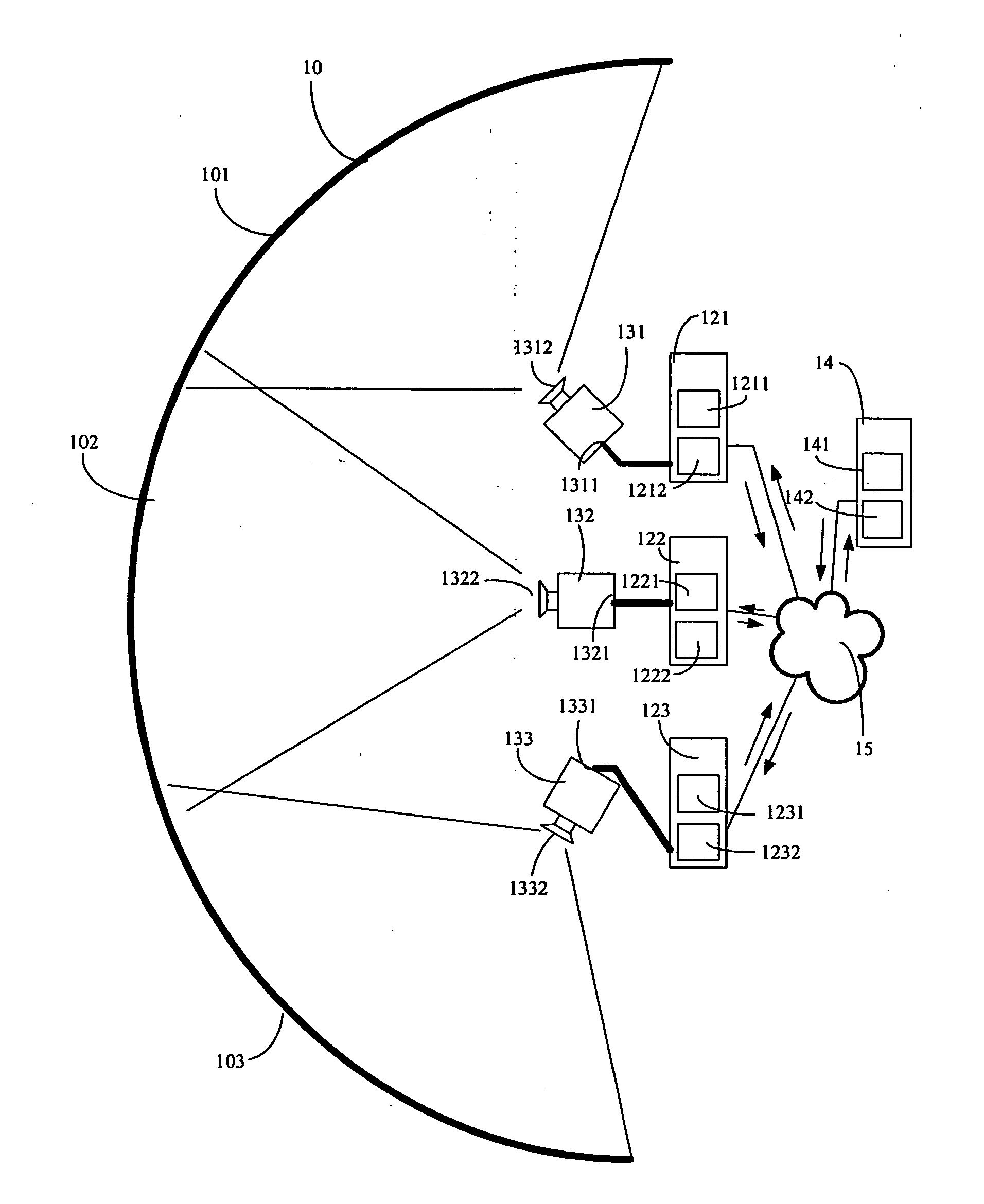
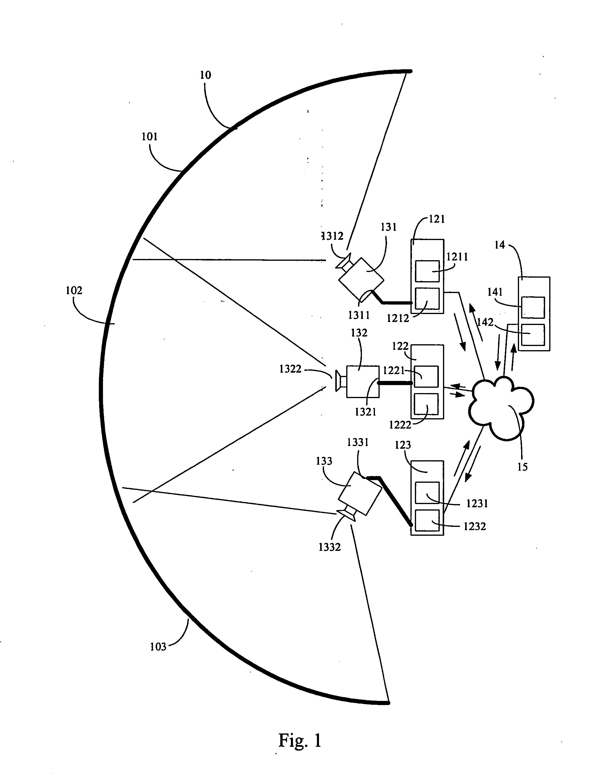
[0035] As shown in FIG. 1, the first embodiment of the projecting system contains a screen 10, a network 15, a number of projectors 131, 132, 133, a number of client electronic devices 121, 122, 123, and a server electronic device 14.

[0036] The screen 10 is defined in terms of several areas 101, 102, 103, corresponding to the projectors 131, 132, 133, respectively. The projectors 131, 132, 133 may be general-purpose digital projectors. They correspond to the client electronic devices 121, 122, 123, respectively. The projectors 131, 132, 133 have their own input terminals 1311, 1321, 1331 and projecting lenses 1312, 1322, 1332. The input terminals 1311, 1321, 1331 connect to the corresponding client electronic devices 121, 122, 123. The client electronic devices 121, 122, 123 provide the projectors 131, 132, 133 the image signals via the input terminals 1311, 1321, 1331. The projectors 131, 132, 133 convert the image signals into the corresponding optical images, which are then proj...

Example

Second Embodiment (3D Spatial Simulation System)

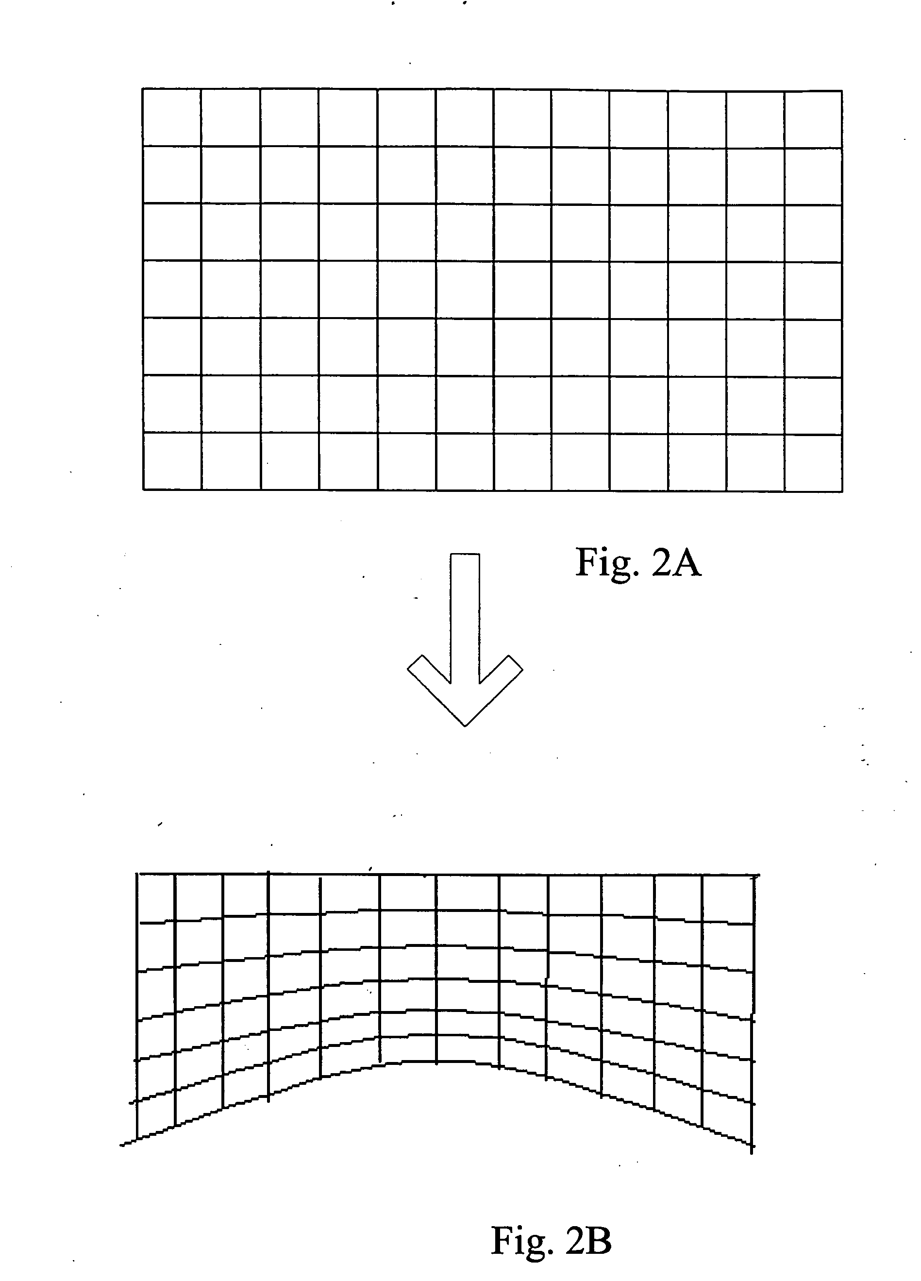
[0063] The invention uses several general-purpose digital projectors to provide an image based on a flexible structure. Therefore, the image can be projected on a surrounding screen with a long, wave, spherical, or even irregular shape.

[0064] To provide a powerful virtual reality system using the above-mentioned structure, we only need to make another OI. For example, we first prepare a 3D space model and store it in the media file. Afterwards, we take the environment parameters of the client electronic devices as the coordinates of the 3D space, observation coordinates, and the amplification ratio and adjust the curve surface parameters and the boundary-smoothing information according to the individual output screens. Moreover, we install an OI for the client electronic devices 14. Using the mouse, joystick, and gloves with motion sensors, the user can enter interactive commands of the 3D space.

[0065] For illustration purposes, we ...

Example

Third Embodiment (Software System / Storage Media)

[0068] It should be pointed out that the invention can combine many general-purpose computers, digital projectors, and network devices (such as the network lines and routers or line collectors). Therefore, another viewpoint of the invention is to make a software system, which is installed by the user on several computers. These computers are interconnected and connected to the digital projectors, forming a projecting system.

[0069] The software system includes a client program and a server program. The client program is installed on several client computers, the server program is installed on the server computer. Since modern computers provide powerful multitasking functions, the server program can also be installed on one or several of the client computers. An embodiment of the system of the client computers and the server computer is shown in FIGS. 4 and 5.

[0070]FIG. 4 shows a general-purpose computer hardware structure of the clie...


PUM


Abstract

A projecting system utilizing a number of projectors to generate an output image includes a plurality of client electronic devices and a server electronic device, which are interconnected via a network. Each client electronic device contains a same divided media file and different environment parameters, and drives a corresponding projector by providing processed image data. The image data are processed by a curved surface calculation. These client electronic devices are synchronized with the server electronic device so that these client electronic devices cooperate to drive corresponding projectors for showing the output image.

Description

BACKGROUND OF THE INVENTION [0001] 1. Field of Invention [0002] The invention relates to a projecting system and, in particular, to a projecting system utilizing a plurality of general-purpose projectors to produce a common image. [0003] 2. Related Art [0004] With rapid progresses in electronic and information technologies, electronic devices and computers evolve from simple text interfaces to multimedia interfaces today, rendering more versatile applications in human life. [0005] Generally speaking, multimedia files include both static and dynamic images, music, voices, and various sound effects. The visual presentation, in particular, plays an important role. For example, movies, interactive games, and applications of virtual reality all make a lot use of dynamic images. [0006] Currently, tools for visual presentations include the combinations of playing circuits and the cathode ray tube (CRT), liquid crystal display (LCD), or plasma television screen. However, these screens are o...

Claims


Application Information

Patent Timeline
IPC IPC(8): G02B27/18G03B21/00G03B21/14G03B21/26G03B37/04G09G5/00G09G5/36H04N5/74H04N13/363
CPCG03B21/14G03B37/04H04N13/0459H04N13/0429H04N9/3147H04N13/332H04N13/363
Inventor HSIUNG, CHAO-WANG
Owner VIVAVR TECH
Why Eureka
Try Eureka