

Solid electrolytic capacitor
- Summary
- Abstract
- Description
- Claims
- Application Information
AI Technical Summary
Benefits of technology
Problems solved by technology
Method used
Image

Examples
embodiment 1
[0016] Embodiment 1
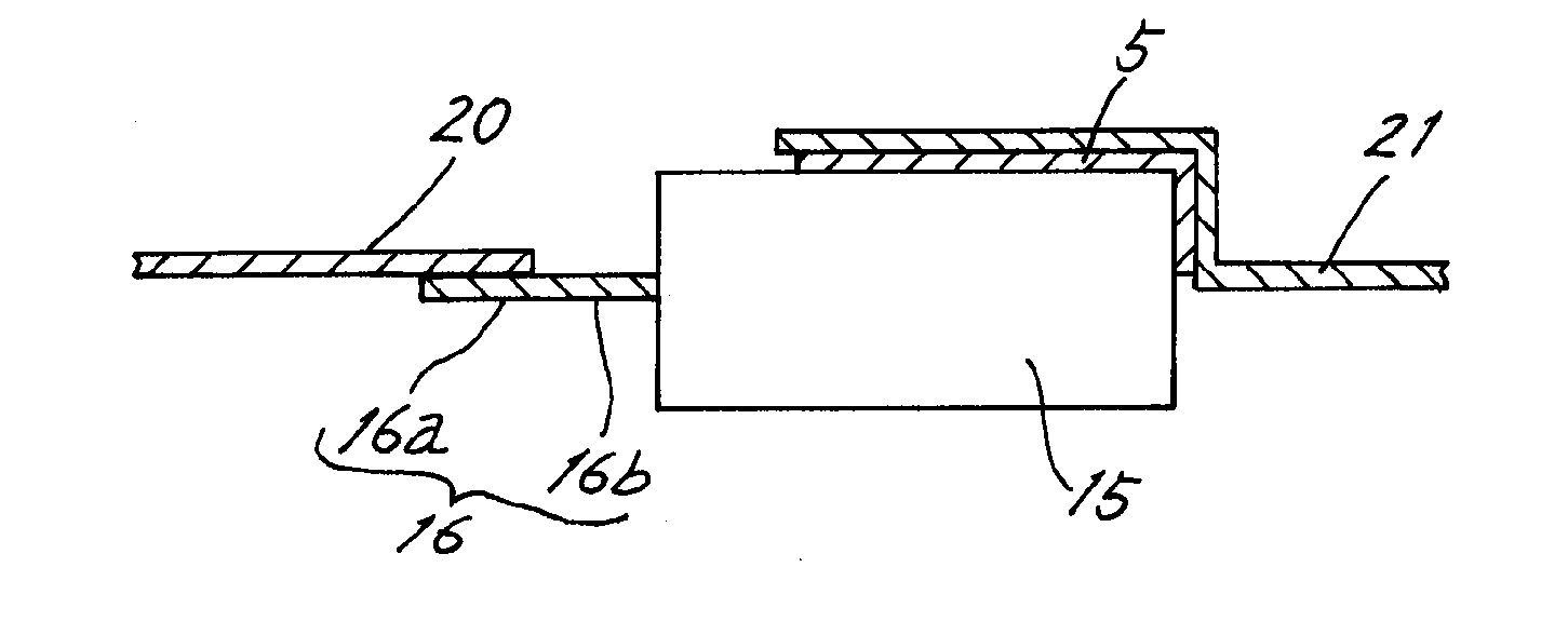
[0017] The overall structure of a solid electrolytic capacitor (8) of the present invention is similar to that of the conventional solid electrolytic capacitor shown in FIG. 8. An anode lead frame (20) is formed using copper or an alloy whose principal component is copper, for example.
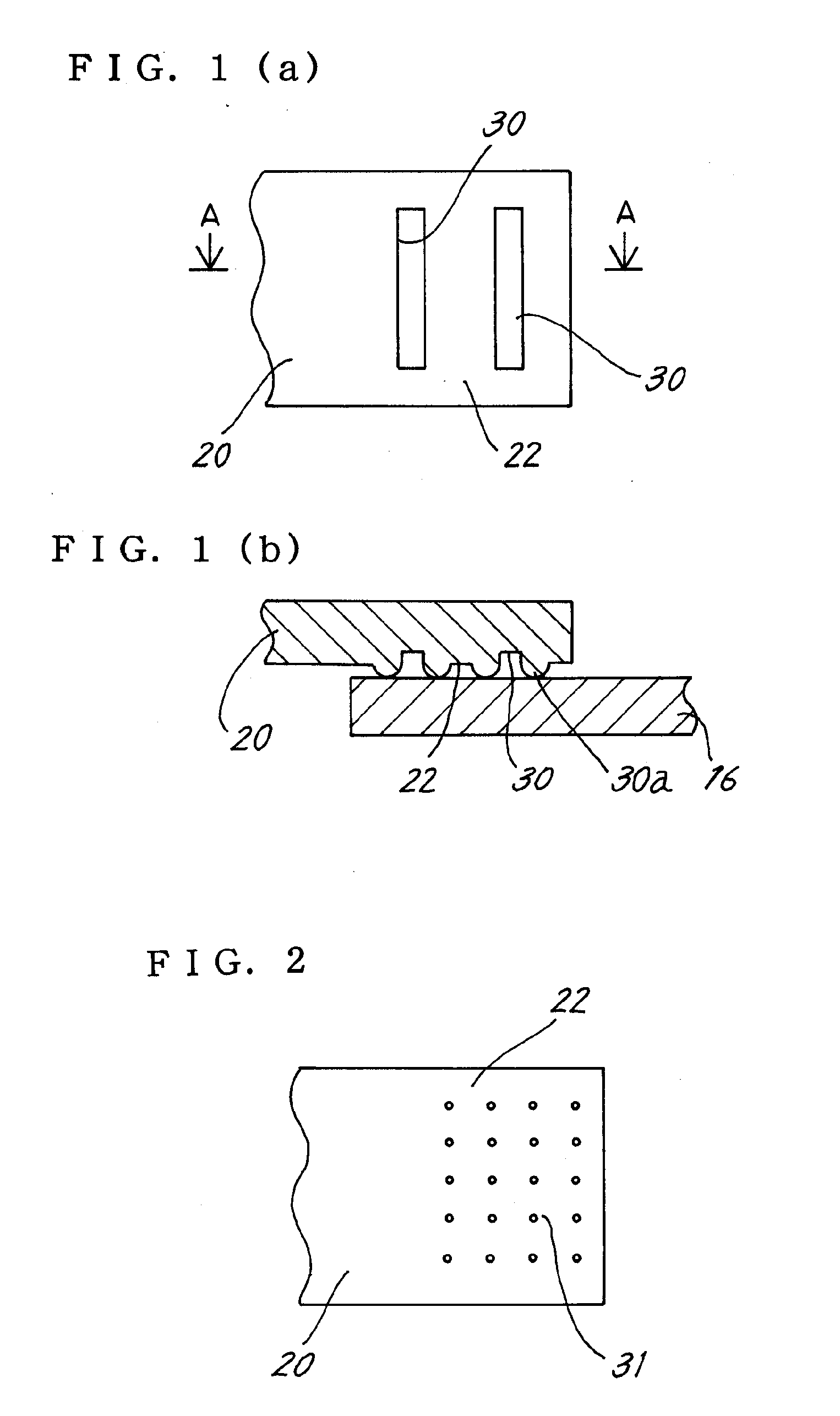
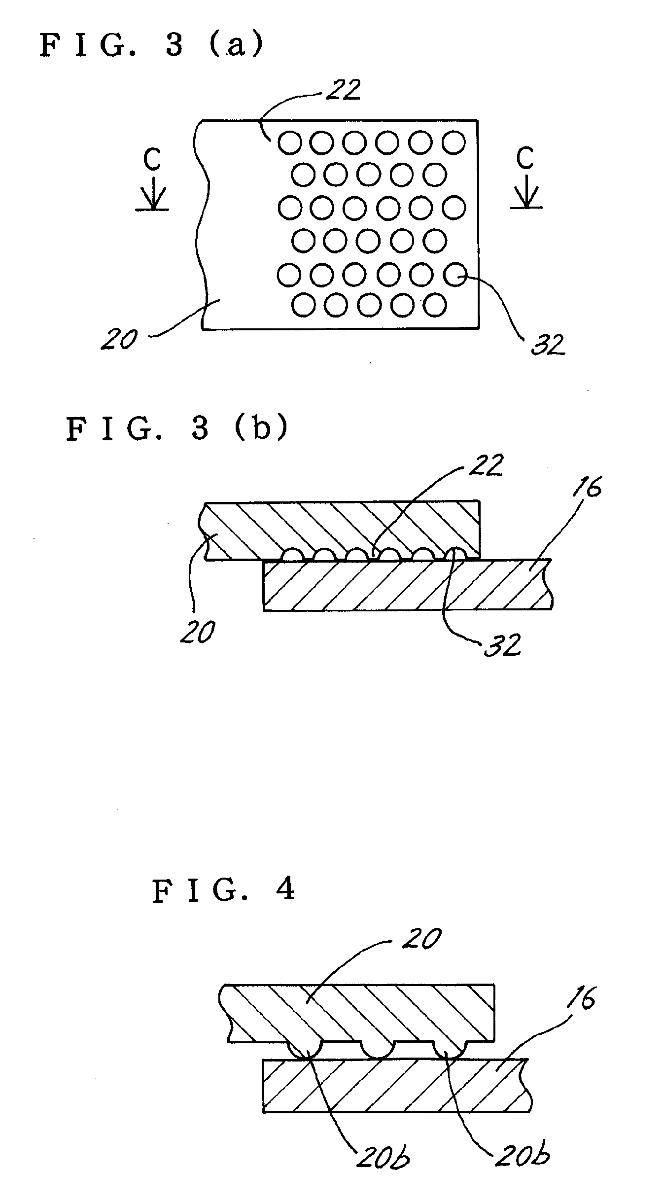
[0018]FIG. 1(a) is a bottom view showing a junction face (22) of the anode lead frame (20) that is connected to the anode lead (16) and FIG. 1(b) is a cross-sectional view taken along the A-A line of FIG. 1(a). Grooves (30) that are substantially perpendicular to the longitudinal direction of the anode lead frame (20) are provided in the junction face (22). The junction face (22) and the anode lead (16) contact each other only at the edge portions of the grooves (30), and the area in which the anode lead frame (20) and the anode lead (16) are in contact is small.
[0019] Therefore, the contact resistance between the anode lead frame (20) and the anode lead (16) increases. In other wo...
embodiment 2
[0027] Embodiment 2
[0028] In the embodiment above, the contact resistance enlarging portion is formed on the anode lead frame (20), but in this embodiment, the contact resistance enlarging portion is formed on the plate-shaped anode lead (16).
[0029]FIG. 6(a) is a lateral view of the anode lead (16) and the anode lead frame (20) and FIG. 6(b) is a bottom view thereof. A front end portion (16a) of the anode lead (16) is processed to an angular shape and the width of the front end portion (16a) is narrower than the width W of the base end portion (16b). The anode lead (16) and the anode lead frame (20) are fastened by resistance welding at a welding portion (50) of this front end portion (16a).
[0030] Also in this structure, the area in which the anode lead frame (20) and the anode lead (16) are in contact is small. Therefore, the contact resistance between the anode lead frame (20) and the anode lead (16) increases, and when performing resistance welding, joule heat tends to increase...
PUM
 Abstract
Description
Claims
Application Information