High extinction ratio fiber interferometer

a fiber interferometer and high extinction ratio technology, applied in the field of communication system demodulation of optical differential phase shift keying (dpsk) demodulation, can solve the problem of dramatic deformation of er, and achieve the effect of simple, elegant solution, and greatly reduced probability of error

Active Publication Date: 2005-03-17
THE BOEING CO
View PDF1 Cites 6 Cited by
  • Summary
  • Abstract
  • Description
  • Claims
  • Application Information

AI Technical Summary

Benefits of technology

[0011] The present invention represents a very significant advance in the laser communications technology area, as it provides a simple, elegant solution to DPSK demodulation. Furthermore, because embodiments of the invention do not require additional optical elements or control loops while still increasing the extinction ratio, the probability of error is greatly reduced. A 50:50 coupler can be used to implement the DPSK demodulator embodiment where the delay length corresponds to approximately one bit of the modulated signal.
[0012] Further, embodiments of the invention are much lighter than the current art, utilizing a Mach-Zhender interferometer; estimates indicate a weight decrease of as much as 75%. The present invention also offers a similar reduction in size.
[0013] Embodiments of the present invention are also simple to fabricate. Thus, it can be produced by technicians having only basic skills. In contrast, with the Mach-Zhender approach, only a very limited number of technicians possess the skill necessary to fabricate an acceptable interferometer. The reflective ends can be cleaved and coated with silver, however, gold coating should produce better results.
[0014] In addition, inter-satellite optical communication represents a great leap forward in the exploding field of telecommunications and DPSK offers a very efficient single-wavelength coding method. Hence, DPSK is very attractive for those pursuing laser communication in an inter-satellite system. The present invention provides a simple, compact and efficient DPSK demodulation apparatus and method for use in such applications.

Problems solved by technology

Because these SOPs are randomly scrambled, optical interference is degraded which dramatically degrades the ER.

Method used


Image

  • High extinction ratio fiber interferometer
  • High extinction ratio fiber interferometer
  • High extinction ratio fiber interferometer

Examples


Embodiment Construction

[0019] In the following description of the preferred embodiment, reference is made to the accompanying drawings which form a part hereof, and in which is shown by way of illustration specific embodiments in which the invention may be practiced. It is to be understood that other embodiments may be utilized and structural changes may be made without departing from the scope of the present invention.

[0020] 1. Overview

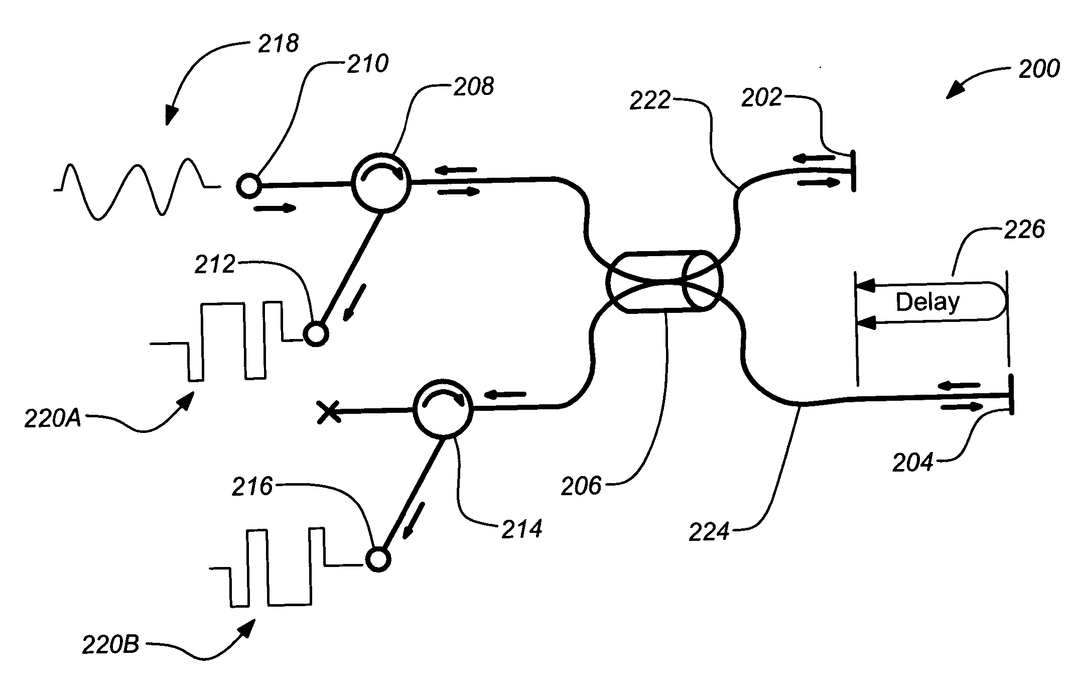
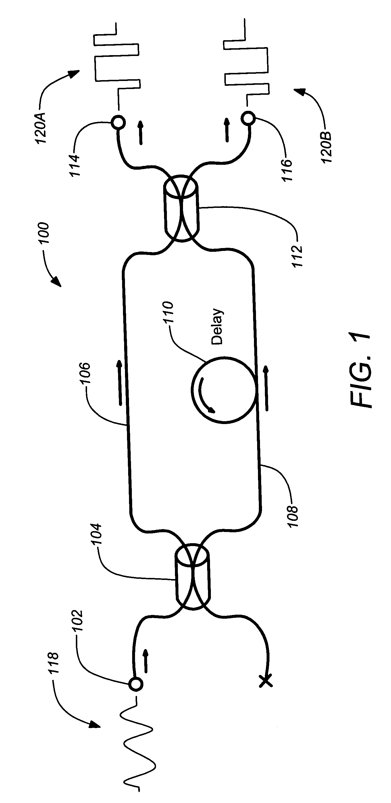
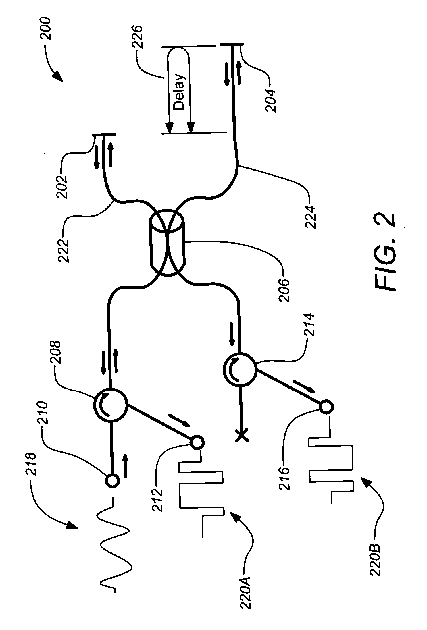
[0021] Embodiments of the present invention generally encompass a Michelson fiber interferometer which can be used in an optical DPSK demodulator. The purity of the interference is guaranteed by cleaving the optical fibers of the interferometer such that the path lengths are less than approximately 10 cm. This defeats the random variations in SOP otherwise present between the optical fibers.

[0022] The description of this invention rests on the principles of optical DPSK communications. The essential idea of optical DPSK is that bits are encoded onto an optical carrier (...


PUM


Abstract

A high extinction ratio interferometer is disclosed. The interferometer includes a first and second optical fiber each having a first end and a reflective end and an optical coupler for coupling the first optical fiber and the second optical fiber between their first ends and their reflective ends. The first optical fiber provides a first optical path from the optical coupler to its reflective end and back to the optical coupler and the second optical fiber provides a second optical path from the optical coupler to its reflective end and back to the optical coupler. The second path is greater than the first path by a delay length and the first path and the second path are each less than approximately 20 cm. The interferometer finds application as a differential phase shift keyed (DPSK) demodulator, particularly useful in a satellite system employing inter-satellite communication.

Description

BACKGROUND OF THE INVENTION [0001] 1. Field of the Invention [0002] The present invention relates to apparatuses and methods for implementing optical differential phase shift keying (DPSK) demodulation in a communication system, and particularly for implementing optical DPSK demodulation in a satellite communication system. [0003] 2. Description of the Related Art [0004] Optical DPSK modulation schemes generally allow a 3 dB signal gain over conventional on-off keyed systems, which make them ideal for satellite communications. Optical DPSK receivers require a demodulator, typically a Mach-Zhender interferometer as is known in the art, to convert the bit stream from phase-shift keyed to on-off Keyed. [0005] The efficiency of an optical DPSK communication link can be characterized by its bit-error-rate (BER). The BER is greatly affected by the quality of the demodulator. In fact, in many applications a very pure optical interference is required to achieve acceptable BER. This purity c...

Claims


Application Information

Patent Timeline
Patent Type & Authority Applications(United States)
IPC IPC(8): G02B6/28
CPCG02B6/2861
Inventor CONWAY, JOSHUA A.HOULT, WILLIAM S. JR.
Owner THE BOEING CO
Why Eureka
Try Eureka