
Material removal and dispensing devices, systems, and methods

Inactive Publication Date: 2005-03-17
IRM
View PDF17 Cites 89 Cited by
  • Summary
  • Abstract
  • Description
  • Claims
  • Application Information

AI Technical Summary

Benefits of technology

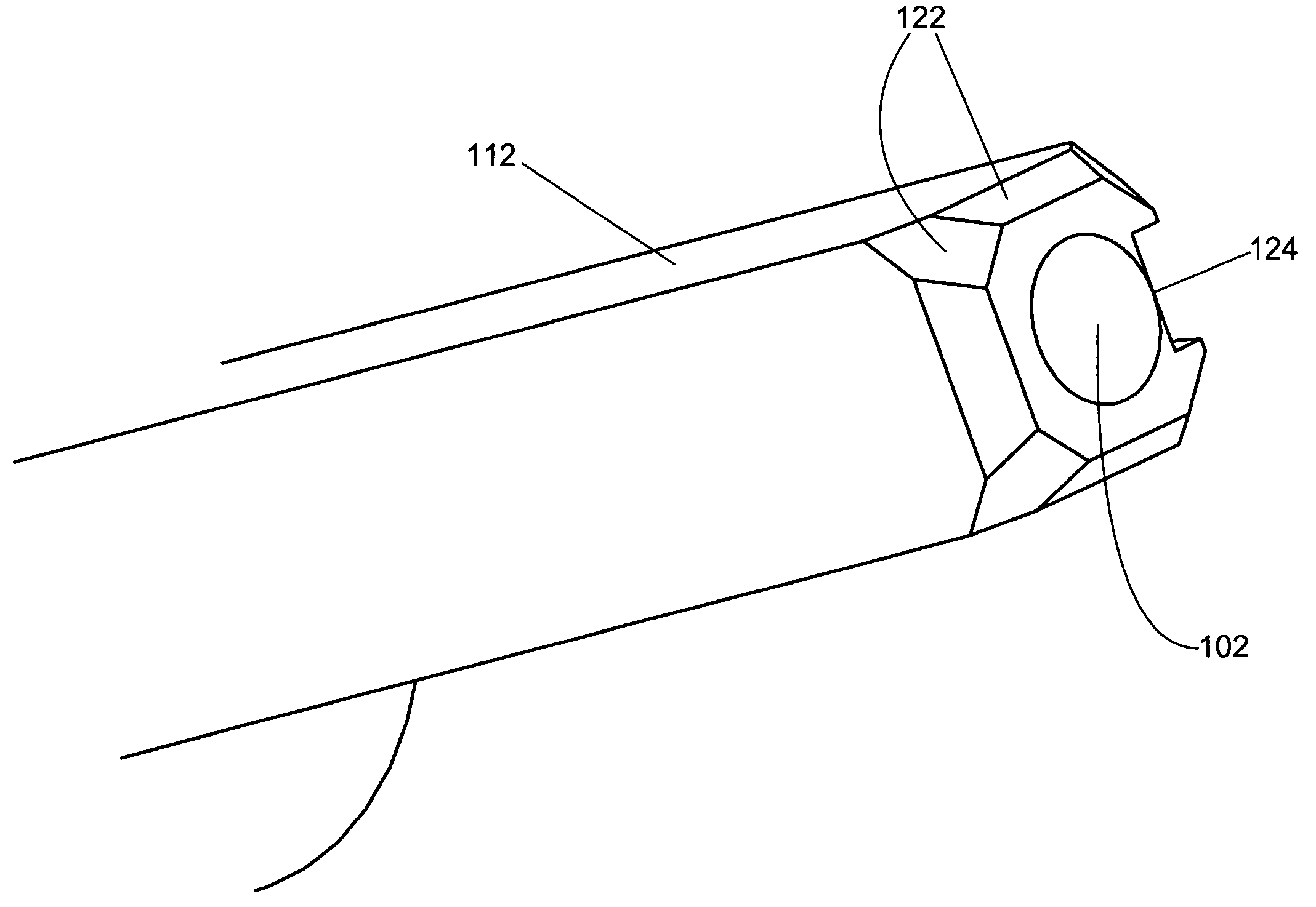
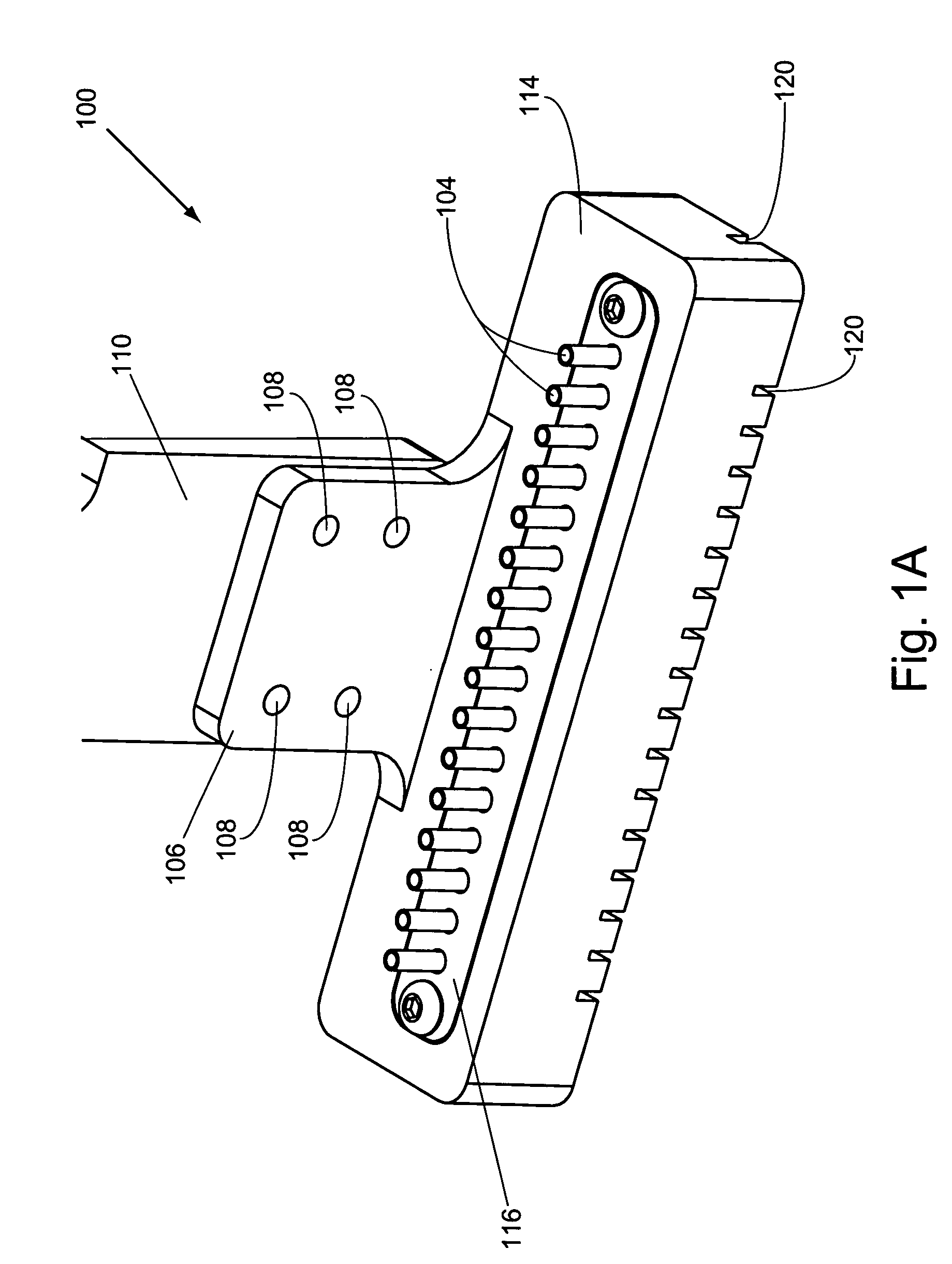
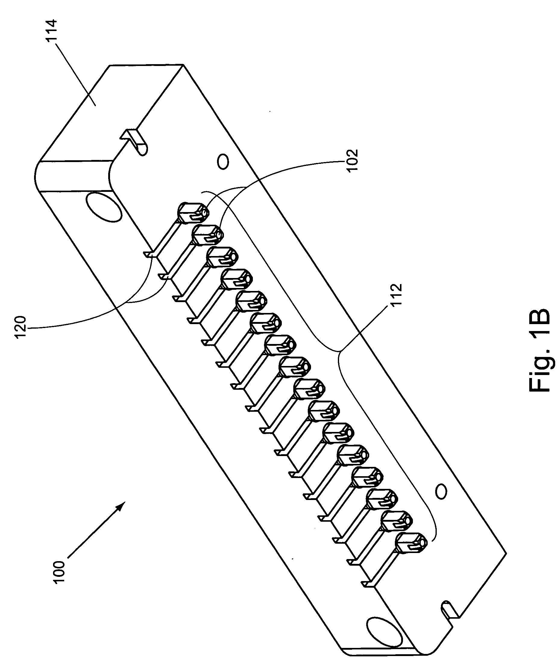
[0008] In one aspect, the invention relates to a material removal head for removing materials from one or more wells of a multi-well plate. The material removal head includes at least one tip that a) comprises at least one vent opening, at least one inlet and at least one outlet, which inlet communicates with the outlet (e.g., includes a channel or other cavity disposed through the tip), and b) is structured such that when the inlet is disposed proximal to a selected well from which a material is to be removed, the tip forms a barrier between the selected well and at least one adjacent well. Further, when the outlet is operably connected to a negative pressure source, air is drawn through the vent opening and into the inlet, thereby noninvasively removing a material from the selected well while the barrier prevents cross-contamination of the adjacent well. In some embodiments, the tip is coupled to a body structure of the material removal head by a resilient coupling, e.g., to account for surface variations of multi-well plates, to prevent damage to the tips and to multi-well plates, etc. when materials are noninvasively removed from the plates. In some embodiments, material removal heads of the invention include one or more manifolds such that, for example, multiple inlets can communicate with one or more outlets, or multiple outlets can communicate with one or more inlets.
[0024] In another aspect, the invention provides a dispensing system that includes a) at least one dispense head comprising at least one dispenser that is structured to dispense material into one or more wells of at least one multi-well plate. The dispenser is angled (e.g., between about 0° and about 90°) relative to a Z-axis so that the material is dispensed onto the sides of the wells when the dispenser is operably connected to a material source and the material is dispensed from the dispenser. As described herein, this minimizes the formation of bubbles when fluidic materials are dispensed into the wells among other advantages. In addition, the dispensing system also includes b) at least one positioning component that is structured to position one or more multi-well plates relative to the dispense head.

Problems solved by technology

Pre-existing devices used to remove these fluidic materials from the wells typically utilize syringe or vacuum pumps having tips that invasively aspirate the fluids from the wells.
The invasiveness and frequent tip washings associated with these approaches significantly limit assay throughput.
In addition, the openings to these tips generally have small internal dimensions (e.g., diameters) that are easily plugged or otherwise obstructed by cells or other debris aspirated from the wells.
In many instances, this leads to incompletely emptied wells, which can ultimately yield biased assay results.
Plugged tips in these pre-existing devices, which can be difficult to detect, must generally be unplugged or replaced.
This “down time” further limits assay throughput.

Method used


Image

  • Material removal and dispensing devices, systems, and methods
  • Material removal and dispensing devices, systems, and methods
  • Material removal and dispensing devices, systems, and methods

Examples


Embodiment Construction

[0052] I. Definitions

[0053] Before describing the present invention in detail, it is to be understood that this invention is not limited to particular devices, systems, kits, or methods, which can, of course, vary. It is also to be understood that the terminology used herein is for the purpose of describing particular embodiments only, and is not intended to be limiting. Further, unless defined otherwise, all technical and scientific terms used herein have the same meaning as commonly understood by one of ordinary skill in the art to which this invention pertains. In describing and claiming the present invention, the following terminology and grammatical variants will be used in accordance with the definitions set out below.

[0054] The term “noninvasive” or “non-contact” refers to an act that does not involve penetrating or contacting a surface of material to be removed from a multi-well plate. Material surfaces typically include surfaces of fluidic and / or solid materials (e.g., dr...


PUM


Abstract

The present invention provides material removal heads and devices for noninvasively removing materials from the wells of multi-well plates. The material removal heads of the invention are structured to prevent cross-contamination among wells of multi-well plates as materials are removed from the plates. The invention also provides dispense heads and devices that include angled dispensers. Related systems, kits, and methods are additionally provided.

Description

CROSS-REFERENCES TO RELATED APPLICATIONS [0001] This application claims the benefit of U.S. Provisional Application No. 60 / 461,638, filed Apr. 8, 2003, the disclosure of which is incorporated by reference in its entirety for all purposes.COPYRIGHT NOTIFICATION [0002] Pursuant to 37 C.F.R. § 1.71(e), Applicants note that a portion of this disclosure contains material which is subject to copyright protection. The copyright owner has no objection to the facsimile reproduction by anyone of the patent document or patent disclosure, as it appears in the Patent and Trademark Office patent file or records, but otherwise reserves all copyright rights whatsoever. BACKGROUND OF THE INVENTION [0003] The multi-well plate has rapidly become a standard format utilized in many modern pharmaceutical discovery and development procedures, including various biochemical and cell-based assays. For example, numerous common cell-based assay steps are routinely performed in parallel in multi-well plates. Th...

Claims


Application Information

Patent Timeline
IPC IPC(8): B01DB01L3/00B01L3/02B01L99/00G01N35/10
CPCB01L3/021B01L3/5085B01L2200/026B01L2200/0689B01L99/00B01L2300/048B01L2300/0829B01L2400/049G01N35/1081B01L2200/141B01L13/02
Inventor MICKLASH, KENNETH J. IIDOWNS, ROBERT CHARLESCHANG, JIM YUCHENMAINQUIST, JAMES KEVIN
Owner IRM
Learn More