System and method for power control calibration and a wireless communication device

a wireless communication device and power control technology, applied in power management, transmission monitoring, transmission monitoring, etc., can solve the problems of uncorrelated pn codes, signal transmitted from one cdma wireless device appears as noise to other cdma devices operating at the same frequency and in the same geographic region, and the signal itself cannot be used directly to control the gain of the vga

Inactive Publication Date: 2005-03-17
QUALCOMM INC
View PDF28 Cites 15 Cited by
  • Summary
  • Abstract
  • Description
  • Claims
  • Application Information

AI Technical Summary

Problems solved by technology

The PN codes are mathematically uncorrelated to each other such that one CDMA wireless device cannot decode the radio frequency (RF) signal intended for another CDMA device.
As a result, a signal transmitted from one CDMA wireless device appears as noise to other CDMA devices operating at the same frequency and in the same geographic region.
However, these are engineering implementations within the skill of the design engineer.
Although the RSSI is an indicator of received signal strength, the signal itself cannot be used directly to control the gain of the VGA 18 because of the inherent nonlinearities of the variable gain input.
Unfortunately, the variable gain input versus gain of the VGA 18 is not linear.
However, process variations and design limitations of the VGA 18 make it virtually impossible to achieve ideal linear relationship. FIG. 3 also illustrates the actual relationship between the control voltage VCONT and gain of the VGA 18.
The drawback of this process is that each individual wireless device must be carefully calibrated so that the linearizer 40 is customized for virtually every device.
Because of the importance of power control in a CDMA wireless system, the calibration of the variable gain amplifier in the transmitter of a wireless device is even more important and time-consuming than the process described above with respect to the receiver portion of a wireless communication device.
As those skilled in the art will recognize, this is a time-consuming process, which is difficult to perform.
Those skilled in the art will appreciate that such an enormous number of calibration steps, each of which requires external test equipment, is very time-consuming in the production process and adds significantly to the cost of the product.

Method used


Image

  • System and method for power control calibration and a wireless communication device
  • System and method for power control calibration and a wireless communication device
  • System and method for power control calibration and a wireless communication device

Examples


Embodiment Construction

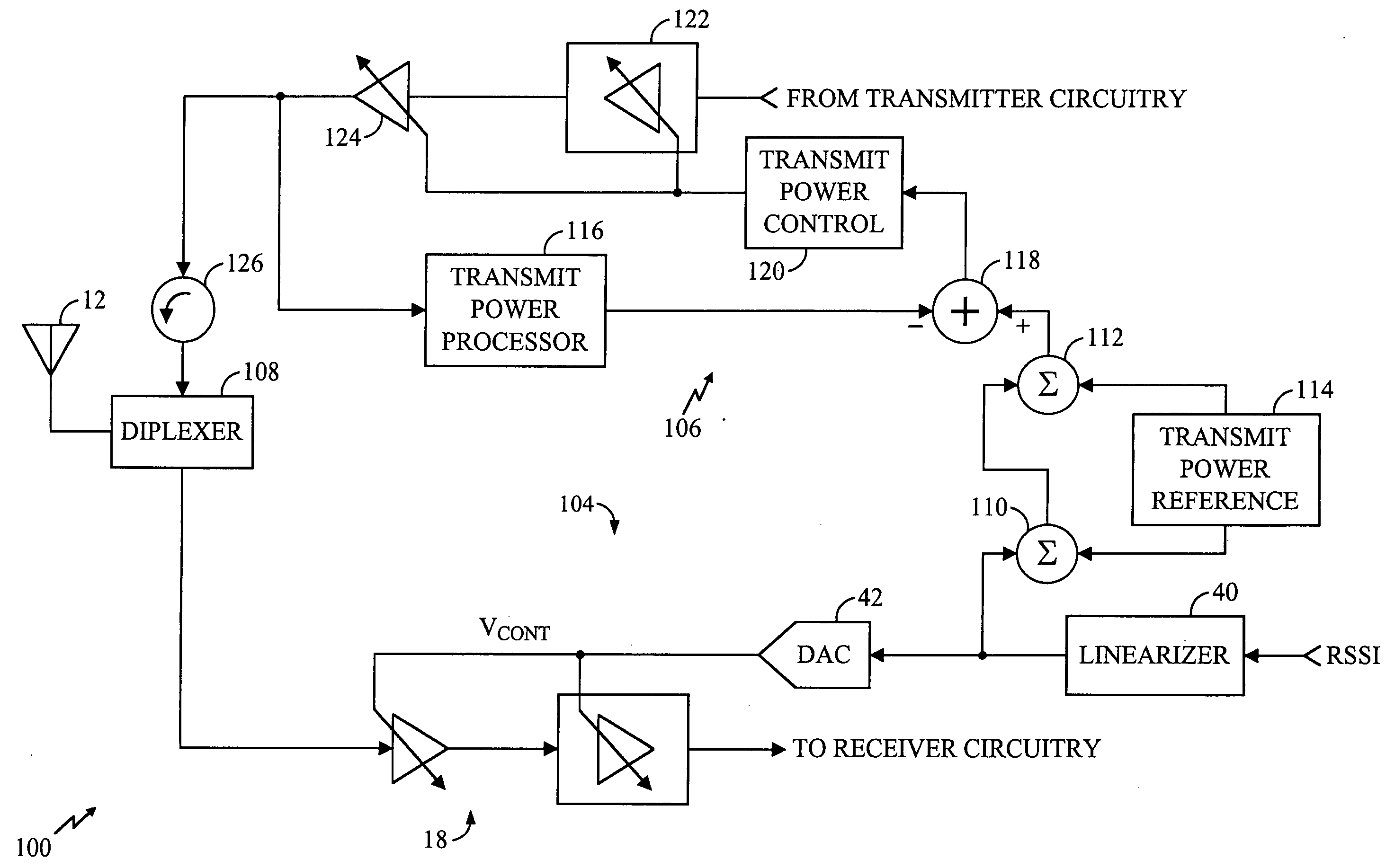
[0034] The presently disclosed subject matter is directed to a technique to control the transmit power and overcome the inherent nonlinearities of control voltage of a variable gain amplifier. In one exemplary embodiment, a dynamic feedback loop is provided that permits precise control of transmit power without the need for a linearizer. Although the importance of power control in a CDMA system has been discussed and the examples presented herein are implementations within a CDMA device, virtually all wireless devices utilize variable gain amplifiers and suffer from the effects of nonlinearity in the gain control. The presently disclosed subject matter provides a solution to the problem of nonlinear gain control and is broadly applicable to any wireless device. The presently disclosed subject matter is not limited to CDMA technology.

[0035]FIG. 4 is a functional block diagram of one exemplary embodiment of the presently disclosed subject matter to control transmit power. In the exam...


PUM


Abstract

A technique for calibrating the open-loop transmit power of a wireless communication device overcomes the inherent nonlinearities in the gain control input of a variable gain amplifier (VGA). In one embodiment, a feedback circuit generates a signal indicative of the transmit power. This signal is compared with a desired transmit power level, which comprises an open-loop gain component and a closed-loop gain component. The desired transmit power level is compared with the actual transmit power level and an error signal is generated. The error signal is used to alter the gain of the VGA in the transmitter to thereby adjust the actual transmit power level to correspond with the desired transmit power level. In alternative embodiment, the receiver portion, which also contains a VGA, is pre-calibrated in a conventional manner. During a transmitter calibration process, the transmitter is coupled to the receiver input through a mixer and filter. The pre-calibrated receiver determines the actual transmit power level. The difference is used to generate error correction data to adjust for non linearities in the gain control input of the transmitter VGA.

Description

RELATED APPLICATIONS [0001] This application is a divisional of U.S. patent application Ser. No. 10 / 177,057, filed on Jun. 20, 2002, which claims priority to U.S. Provisional Application No. 60 / 301,184, filed on Jun. 26, 2001.FIELD OF THE INVENTION [0002] The disclosed subject matter is directed generally to power control in a wireless communication device and, more particularly, to a system and method for calibration of open-loop power control in a wireless communication device. BACKGROUND OF THE INVENTION [0003] Wireless communication devices are widely used throughout the world. Such wireless devices use radio frequency components, including transmitters and receivers. Proper operation of wireless devices requires the careful calibration of the transmitter and receiver sections. This is particularly important in some wireless communications schemes, such as code division multiple access (CDMA) technology where multiple users are transmitting simultaneously on the same frequency. ...

Claims


Application Information

Patent Timeline
Patent Type & Authority Applications(United States)
IPC IPC(8): H03G3/30H04B1/00H04B1/04H04B1/40H04B1/707H03G3/20H04B7/005H04B7/26H04B17/00H04J13/00
CPCH04B17/13H04W52/52
Inventor SAHOTA, GURKANWAL SINGH
Owner QUALCOMM INC
Why Eureka
Try Eureka