Method and apparatus for localized drug delivery

a localized drug and device technology, applied in the field of methods, can solve the problems of not being useful in achieving the objectives of yock et al., and achieve the effect of accurate measurement of the infusion spa

Inactive Publication Date: 2005-03-17
GARRISON MICHI +2
View PDF19 Cites 137 Cited by
  • Summary
  • Abstract
  • Description
  • Claims
  • Application Information

AI Technical Summary

Benefits of technology

[0007] In still another embodiment, the system can be constructed such that the catheter with the proximal occlusion device is placed first using a guide wire and / or malleable stylet, such that this catheter acts as a guide for the catheter having the distal occlusion device. It is desirable for the catheter with the proximal occlusion device to be placed in the coronary sinus and certain physical characteristics are desirable for this purpose. These characteristics include a reinforced shaft which can transmit torque in its proximal region (e.g., approximately 50 cm) which does not enter the vasculature. The distal end is more flexible thereby enabling tracking into the venous anatomy. Additionally, the catheter shaft will have a built-in curve, so that the catheter is pointing the correct way to facilitate making a turn into the coronary sinus.
[0009] The catheter system of the present invention may use a coaxial or dual lumen construction for the catheter having the proximal occlusion device and may use a tri-lumen construction for the catheter with the distal occlusion device. In another embodiment, the infusion lumen is the annular space between the two catheters. The amount of space will depend on the infusion flow rate desired. Radio opaque markers may be added to one or both catheters to mark desired points on catheters, e.g., the distal region of each catheter and / or the proximal position of the distal occlusion device. This will help catheter positioning and accurate measurement of the infusion space. Infusion pressure may be regulated passively, e.g., with a spring-controlled reservoir, or actively, e.g., using pressure from the catheter with the distal occlusion device to control a spring force or other mechanism for regulating infusion flow rate.

Problems solved by technology

However, it would not be useful to achieve the objectives of Yock et al.

Method used


Image

  • Method and apparatus for localized drug delivery
  • Method and apparatus for localized drug delivery
  • Method and apparatus for localized drug delivery

Examples


Embodiment Construction

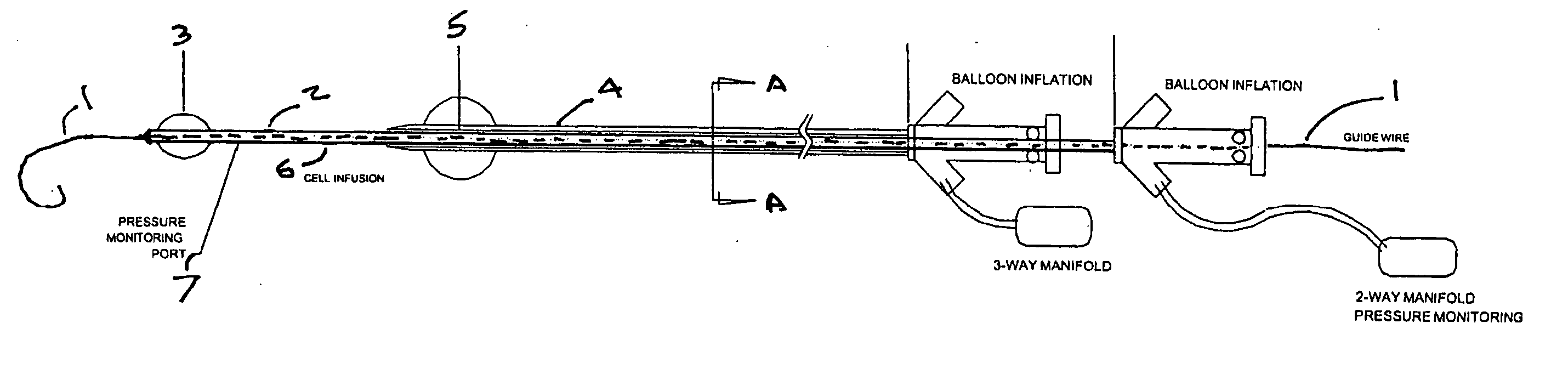
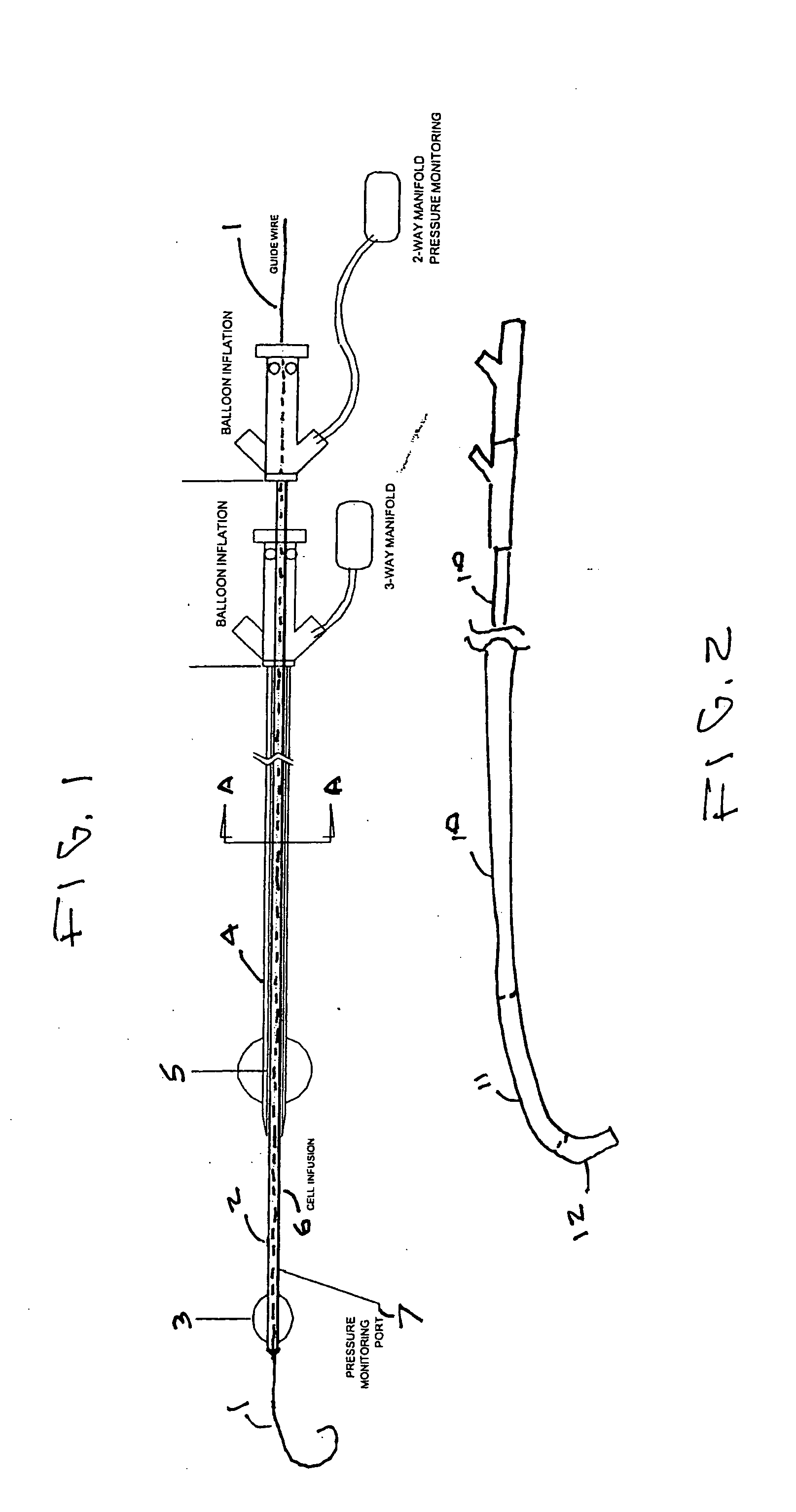
[0015] As can be seen from FIG. 1, one embodiment of the present invention comprises two catheters, each of which is provided with a balloon. The catheter system is constructed such that it can pass over guide wire 1. Inner catheter 2 carries distal occlusion balloon 3. Similarly, outer catheter 4 carries occlusion balloon 5. The section 6 of inner catheter 2 is provided with infusion means, e.g., ports, through which a desired agent, e.g., cells, may be delivered to and administered to the patient through the blood vessel wall surrounding region 6 in the manner disclosed in Yock U.S. Pat. No. 6,346,098. As further shown in FIG. 1, the distal region of inner catheter 2 may also be provided with a pressure monitoring port which measures the pressure of the infusion medium.

[0016]FIG. 2 is a simplified illustration of inner catheter 2 of FIG. 1. Details of the catheter, such as the balloon, have been omitted for purposes of clarity. In FIG. 2, the relatively stiff proximal region of t...


PUM


Abstract

A catheter system for localized administration of agents through the wall of a blood vessel is provided. Various catheter system constructions which use at least two expandable occluding elements to create the localized site are provided. The catheter system may include a catheter with a variable stiffness along its length. The catheter system may also include a hollow guide wire which is coupled to an expandable occluding element.

Description

FIELD OF THE INVENTION [0001] The present invention relates generally to intravascular drug delivery to localized regions. The invention includes a catheter device having two or more occluding members, preferably balloons, associated therewith. BACKGROUND OF THE INVENTION [0002] Methods for localized drug delivery are disclosed in Yock et al. U.S. Pat. No. 6,346,098, which is incorporated by reference, in its entirety, herein. The aforesaid Yock et al. patent describes several ways in which a pressurized system can be used to accomplish retrograde perfusion, alone or in conjunction with other modalities, e.g., energy, to cause disruption or increased porosity in a localized region of the wall of a blood vessel whereby an agent, e.g., a therapeutic substance, is caused to pass through the wall of a blood vessel to produce the desired effect in the tissue surrounding the localized delivery site. Angiogenesis and myogenesis are two particularly desirable uses of the Yock et al. method....

Claims


Application Information

Patent Timeline
Patent Type & Authority Applications(United States)
IPC IPC(8): A61F2/958A61M25/00
CPCA61M25/0032A61M25/1011A61M2025/1052A61M2025/1015A61M2025/0004
Inventor GARRISON, MICHICAMPBELL, PETER F.SALMON, STEVE
Owner GARRISON MICHI
Why Eureka
Try Eureka