Plating apparatus and plating method

a technology of plating apparatus and plating method, which is applied in the direction of electrolysis components, conveyor parts, transportation and packaging, etc., can solve the problems of poor quality of plated film, low material cost, increased cost, etc., and achieves the effect of easy formation of plated film and good quality

Inactive Publication Date: 2005-03-24
EBARA CORP +1
View PDF7 Cites 6 Cited by
  • Summary
  • Abstract
  • Description
  • Claims
  • Application Information

AI Technical Summary

Benefits of technology

[0010] The present invention has been made in view of the above circumstances. It is therefore an object of the present invention to provide a plating apparatus and a plating method which can easily form a plated film having a flat surface and a good quality.

Problems solved by technology

However, in the prior art, when plating is performed, the amount of plated material is different in regions of the surface of the substrate depending on the shape of the interconnect pattern under the influence of distribution of current density or the influence of additives, and hence it is difficult to form a plated film having a uniform thickness over the entire surface of the substrate.
When plating is performed according to such method, more amount of plated material than necessary is deposited, and hence low material cost increases and a longer period of plating time is required.
These ideas or attempts can achieve the object to a certain extent but have a limitation such as a plated film of poor quality.

Method used


Image

  • Plating apparatus and plating method
  • Plating apparatus and plating method
  • Plating apparatus and plating method

Examples


Embodiment Construction

[0059] A plating apparatus and a plating method according to embodiments of the present invention will be described below with reference to the drawings. The following embodiments show examples in which copper as an interconnect material is embedded in fine recesses for interconnects formed in a surface of a substrate such as a semiconductor wafer so as to form interconnects composed of a copper layer. However, it should be noted that other kinds of interconnect materials may be used instead of copper.

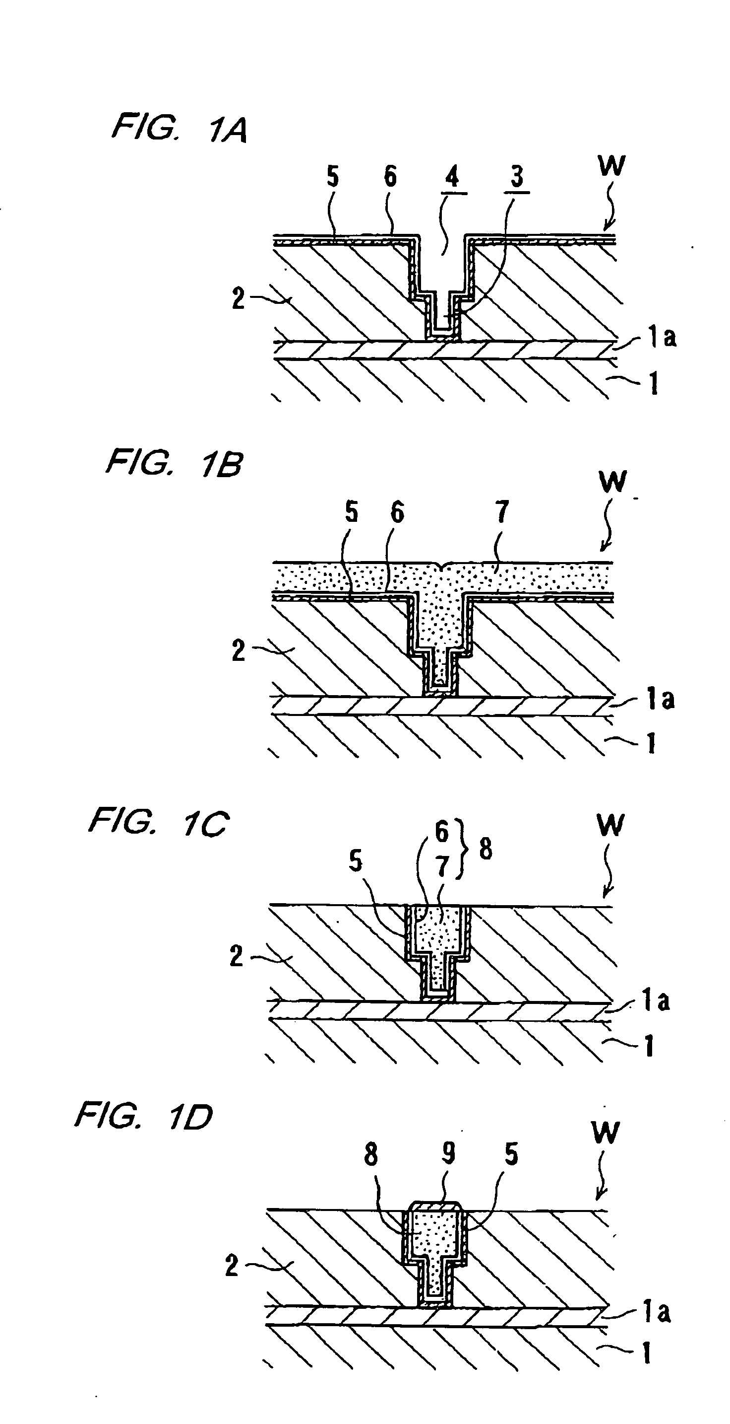
[0060]FIGS. 1A through 1D illustrate an example of forming copper interconnects in a semiconductor device. As shown in FIG. 1A, an insulating film 2, such as an oxide film of SiO2 or a film of low-k material, is deposited on a conductive layer 1a formed on a semiconductor base 1 having formed semiconductor devices. Via holes 3 and trenches 4 are formed in the insulating film 2 by performing a lithography / etching technique so as to provide fine recesses for interconnects. Thereafter, a...


PUM

PropertyMeasurementUnit
diameteraaaaaaaaaa
diameteraaaaaaaaaa
porosityaaaaaaaaaa

Abstract

A plating apparatus is used for filling a fine interconnect pattern formed in a substrate with metal to form interconnects. The plating apparatus includes a cathode unit having a seal member for hermetically sealing a peripheral portion of a surface, to be plated, of the substrate and a cathode electrode which is brought into contact with the substrate to supply current to the substrate; an electrode head disposed so as to be movable toward and away from the surface to be plated and having an anode and a porous member with water retentivity at upper and lower parts of the electrode head; a pressing mechanism for pressing the porous member against the surface, to be plated, of the substrate under a desired pressure; and a driving mechanism for making a relative motion between the porous member and the substrate while the porous member and the surface, to be plated, of the substrate are brought into contact with each other.

Description

BACKGROUND OF THE INVENTION [0001] 1. Field of the Invention [0002] The present invention relates to a plating apparatus and a plating method, and more particularly to a plating apparatus and a plating method used for filling a fine circuit pattern formed in a substrate, such as a semiconductor substrate, with metal (interconnect material) such as copper so as to form interconnects. [0003] 2. Description of the Related Art [0004] Recently, there has been employed a circuit forming method comprising forming fine recesses for interconnects, such as trenches or via holes in a circuit form, in a semiconductor substrate, embedding the fine recesses with copper (interconnect material) by copper plating, and removing a copper layer (plated film) at portions other than the fine recesses by CMP means or the like. In this method, from the viewpoint of reducing loads on subsequent CMP, it is desirable that a copper plated film be deposited selectively in trenches or via holes in a circuit form...

Claims


Application Information

Patent Timeline
Patent Type & Authority Applications(United States)
IPC IPC(8): C25D5/06C25D7/12C25D5/08C25D5/18C25D5/22C25D17/00C25D17/14C25D21/00C25D21/12H01L21/00H01L21/02H01L21/288H01L21/677H01L21/768
CPCC25D5/06C25D17/001H01L21/02068H01L21/02074H01L21/02087H01L21/0209H01L21/288H01L21/2885H01L21/67028H01L21/6708H01L21/67109H01L21/6723H01L21/67751H01L21/7684H01L21/76849H01L21/76877C25D7/123C25D5/08
Inventor KURASHINA, KEIICHINAGAI, MIZUKIYAMAMOTO, SATORUKANDA, HIROYUKIMISHIMA, KOJIBAKER, BRETTKWIETNIAK, KEITHDELIGIANNI, HARIKLIAANDRICACOS, PANOS
Owner EBARA CORP
Why Eureka
Try Eureka