Eureka AIR delivers breakthrough ideas for toughest innovation challenges, trusted by R&D personnel around the world.

Mems-based spectrophotometric system

a spectrophotometric system and spectrophotometric technology, applied in the field of sensors, can solve problems such as difficulties in adapting to portable, especially hand-held, applications

Active Publication Date: 2005-03-24
ALCATEL-LUCENT USA INC +1
View PDF9 Cites 13 Cited by
  • Summary
  • Abstract
  • Description
  • Claims
  • Application Information

AI Technical Summary

Benefits of technology

Problems in the prior art are addressed, in accordance with the principles of the present invention, by a portable spectrophotometric system for detecting one or more target substances. In a representative embodiment, a system of the invention has an optical grating, an array of photo-detectors, and a MEMS device having a movable plate positioned between the grating and the array. Light transmitted through a gaseous sample is dispersed by the grating and is imaged onto the movable plate, which has a plurality of openings corresponding to selected absorption lines of the target substance. A small-amplitude oscillation is imparted onto the plate such that the openings periodically move in and out of alignment with the corresponding intensity features in the image, which modulates electrical signals generated by the corresponding photo-detectors. A lock-in signal processor analyzes the modulation pattern by comparing it to the pattern expected in the presence of the target substance. When a positive correlation between the patterns is established, the system warns the user about the presence of the target substance.

Problems solved by technology

Since exposure to these gases is a health hazard, low concentrations, typically in the range of parts per million (ppm), need to be detected.
However, one problem with prior-art spectrophotometric systems is that they are relatively difficult to adapt for portable, particularly hand-held, applications.

Method used


Image

  • Mems-based spectrophotometric system
  • Mems-based spectrophotometric system
  • Mems-based spectrophotometric system

Examples


Embodiment Construction

Reference herein to “one embodiment” or “an embodiment” means that a particular feature, structure, or characteristic described in connection with the embodiment can be included in at least one embodiment of the invention. The appearances of the phrase “in one embodiment” in various places in the specification are not necessarily all referring to the same embodiment, nor are separate or alternative embodiments mutually exclusive of other embodiments.

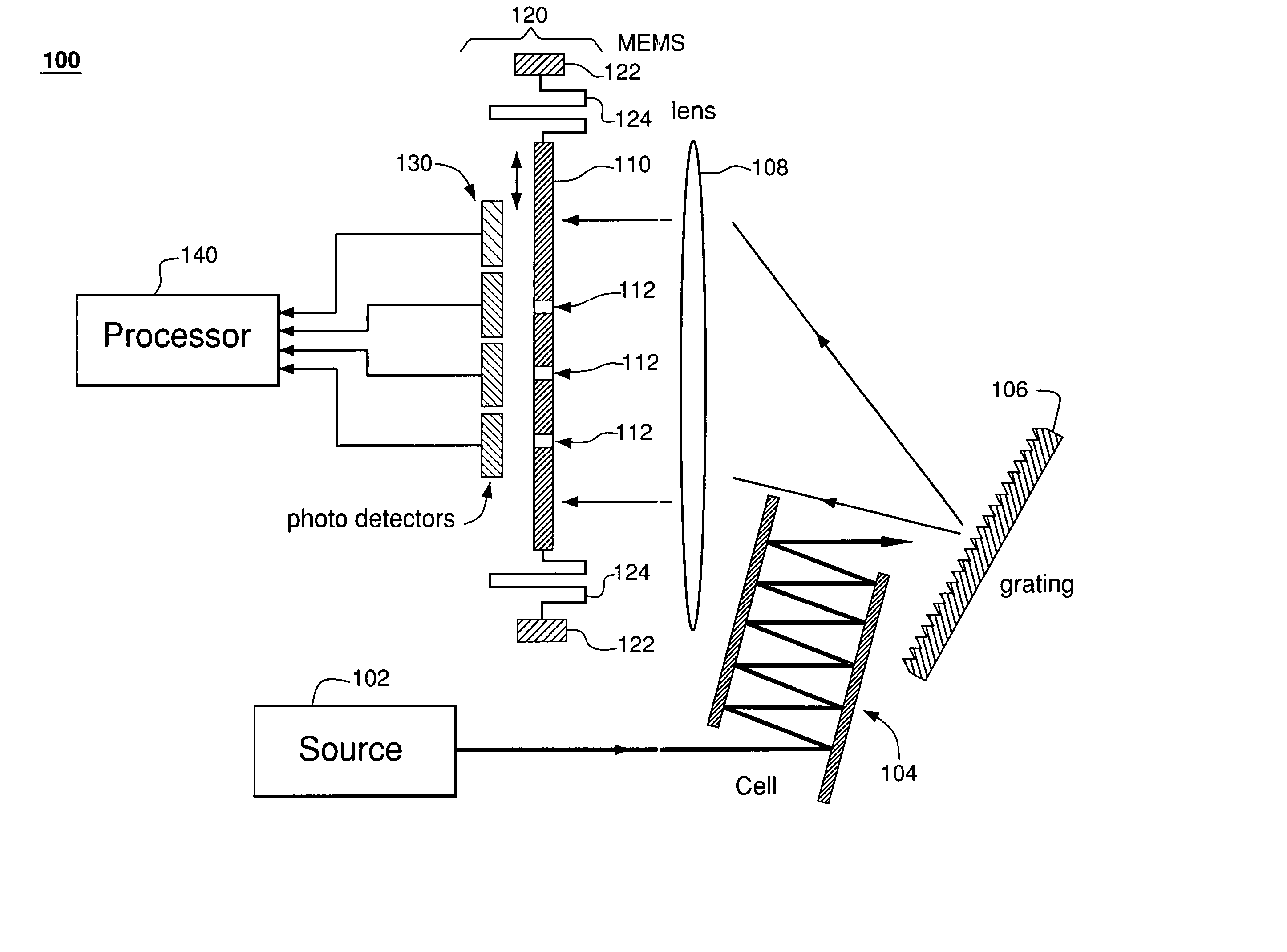
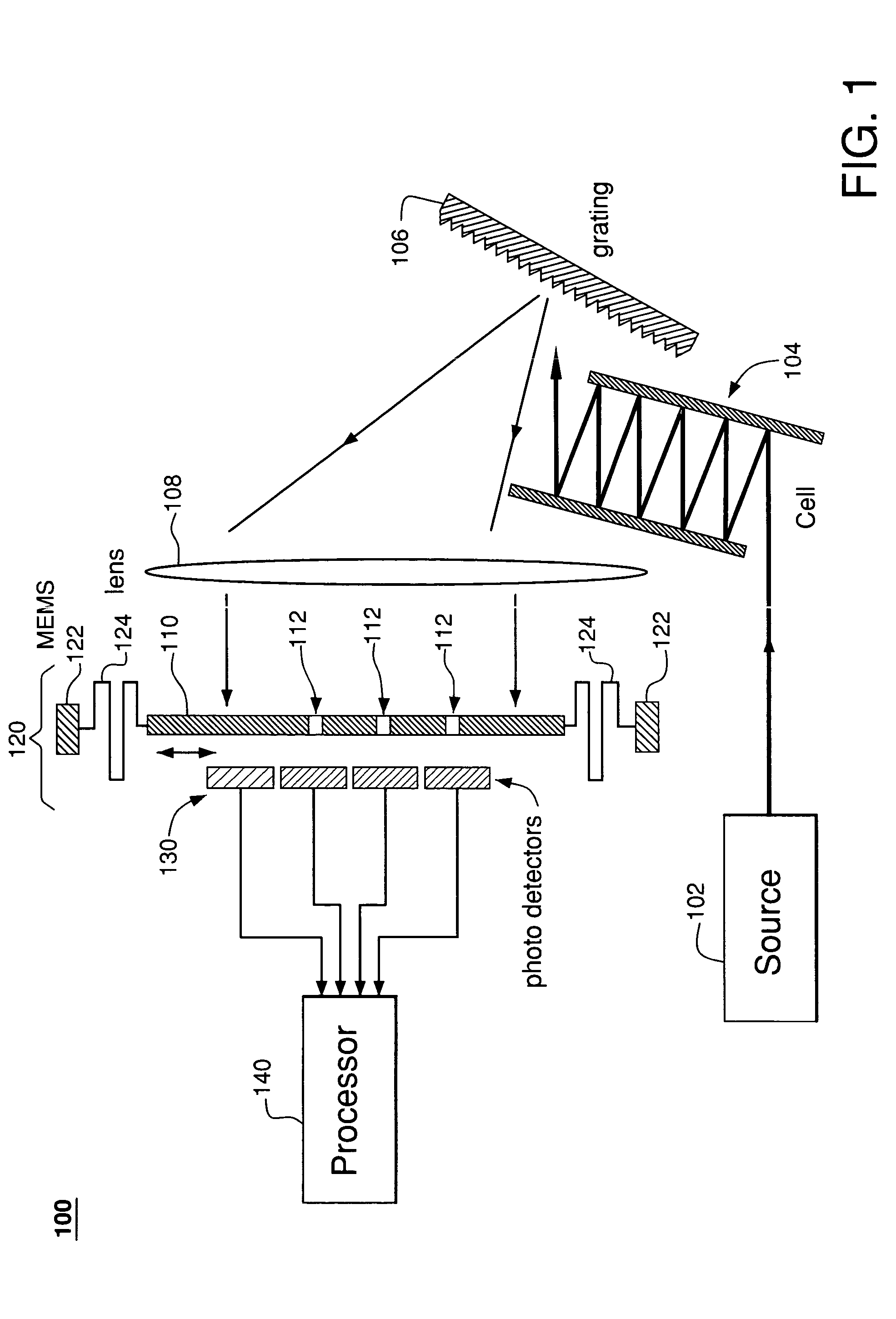
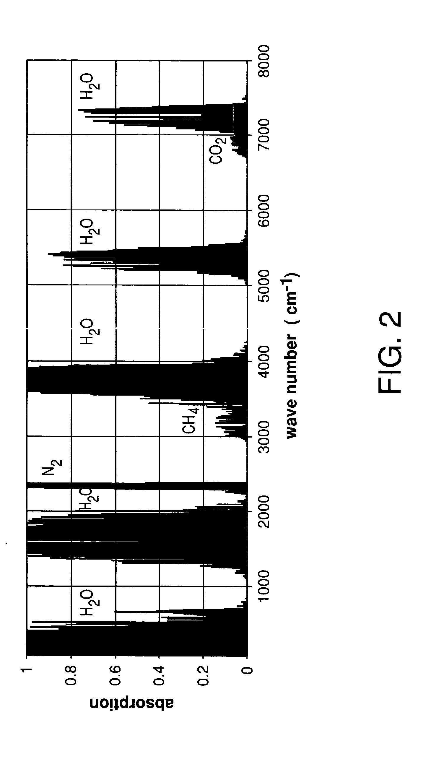
FIG. 1 shows a schematic diagram of a spectrophotometric system 100 according to one embodiment of the present invention. A beam of light generated by a broadband light source 102 is directed through a cell 104 containing a sample to be analyzed. Light transmitted through cell 104 is dispersed in wavelength by a grating 106 and is imaged by a cylindrical lens 108 onto a movable plate 110. The image produced at the surface of plate 110 is a stripe of light, in which different locations along the length of the stripe correspond to differ...


PUM

PropertyMeasurementUnit
wavelengthaaaaaaaaaa
electricalaaaaaaaaaa
concentrationsaaaaaaaaaa

Abstract

A portable spectrophotometric system for detecting one or more target substances. In a representative embodiment, a system of the invention has an optical grating, an array of photo-detectors, and a MEMS device having a movable plate positioned between the grating and the array. Light transmitted through a gaseous sample is dispersed by the grating and is imaged onto the movable plate, which has a plurality of openings corresponding to selected infrared absorption lines of the target substance. A small-amplitude oscillation is imparted onto the plate such that the openings periodically move in and out of alignment with the corresponding intensity features in the image, which modulates electrical signals generated by the corresponding photo-detectors. A lock-in signal processor analyzes the modulation pattern by comparing it to the pattern expected in the presence of the target substance. When a positive correlation between the patterns is established, the system warns the user about the presence of the target substance.

Description

BACKGROUND OF THE INVENTION 1. Field of the Invention The present invention relates to sensors and, more specifically, to optical gas detectors. 2. Description of the Related Art Gas analyzers are used in environmental monitoring, industrial process control, geologic exploration, and medical, analytical, and military applications. For example, gases such as hydrogen sulfide and sulfur dioxide accompany natural gas and are often present in industrial environments. Since exposure to these gases is a health hazard, low concentrations, typically in the range of parts per million (ppm), need to be detected. Different analytical techniques such as optical spectroscopy, mass spectrometry, gas chromatography, electrochemical analysis, etc., may be used for detection of substances present in relatively low concentrations. One particular technique, optical spectrophotometry, is based on the absorption of electromagnetic radiation by the sample in a selected spectral range and is generall...

Claims


Application Information

Patent Timeline
Patent Type & Authority Applications(United States)
IPC IPC(8): G01J3/433G01N21/35
CPCG01J3/02G01J3/0202G01N21/3504G01J3/433G01J3/0229
Inventor GREYWALL, DENNIS S.
Owner ALCATEL-LUCENT USA INC
Why Eureka
Eureka Blog
Learn More