
Molded chip fabrication method and apparatus

a technology of molded chips and fabrication methods, applied in electrical equipment, semiconductor devices, semiconductor/solid-state device details, etc., can solve the problems of increasing the overall cost and complexity, requiring costly fabrication techniques, and not being able to generate white light from active layers, etc., to achieve simple and easy-to-use effects

Inactive Publication Date: 2005-03-24
CREELED INC
View PDF87 Cites 97 Cited by
  • Summary
  • Abstract
  • Description
  • Claims
  • Application Information

AI Technical Summary

Benefits of technology

The present invention provides a method and apparatus for coating semiconductor devices, particularly LEDs, with a controlled layer of "matrix material" having conversion particles. The methods and apparatus are simple and easy to use, and allow for the reproduction of coated semiconductor devices with coating layer geometry and thickness that are substantially the same. The invention allows for the geometry and thickness of the coating layer to be controlled, resulting in LEDs with more uniform color temperature as a function of viewing angle.

Problems solved by technology

One disadvantage of conventional LEDs used for lighting applications is that they cannot generate white light from their active layers.
One disadvantage of this approach is that it requires the use of multiple LEDs to produce a single color of light, increasing the overall cost and complexity.
Combining different LED types to form a white lamp can require costly fabrication techniques and can require complex control circuitry since each device may have different electrical requirements and may behave differently under varied operating conditions (e.g. with temperature, current or time).
One disadvantage of this method is that it is often difficult to control the phosphor layer's geometry and thickness.
As a result, light emitting from the LED at different angles can pass through different amounts of conversion material, which can result in an LED with non-uniform color temperature as a function of viewing angle.
Another disadvantage of the syringe method is that because the geometry and thickness is hard to control, it is difficult to consistently reproduce LEDs with the same or similar emission characteristics.
One disadvantage of this method is that, like the syringe method above, it can be difficult to control the geometry and layer thickness of the phosphor containing polymer.
The stenciling composition may not fully fill the stencil opening such that the resulting layer is not uniform.
These problems can result in LEDs having non-uniform color temperature and LEDs that are difficult to consistently reproduce with the same or similar emission characteristics.
One of the disadvantages of this method is that after the LEDs are covered by the conversion material, the substrate is removed from the electrolyte solution so that LEDs and their conversion material can be covered by a protective epoxy.
Another disadvantage of this process is that the electric field in the electrolyte solution can vary such that different concentrations of conversion material can be deposited across the LEDs.
The electrolyte solution can be stirred to prevent settling, but this presents the danger of disturbing the particles already on the LEDs.

Method used


Image

  • Molded chip fabrication method and apparatus
  • Molded chip fabrication method and apparatus
  • Molded chip fabrication method and apparatus

Examples


Embodiment Construction

Coating Methods

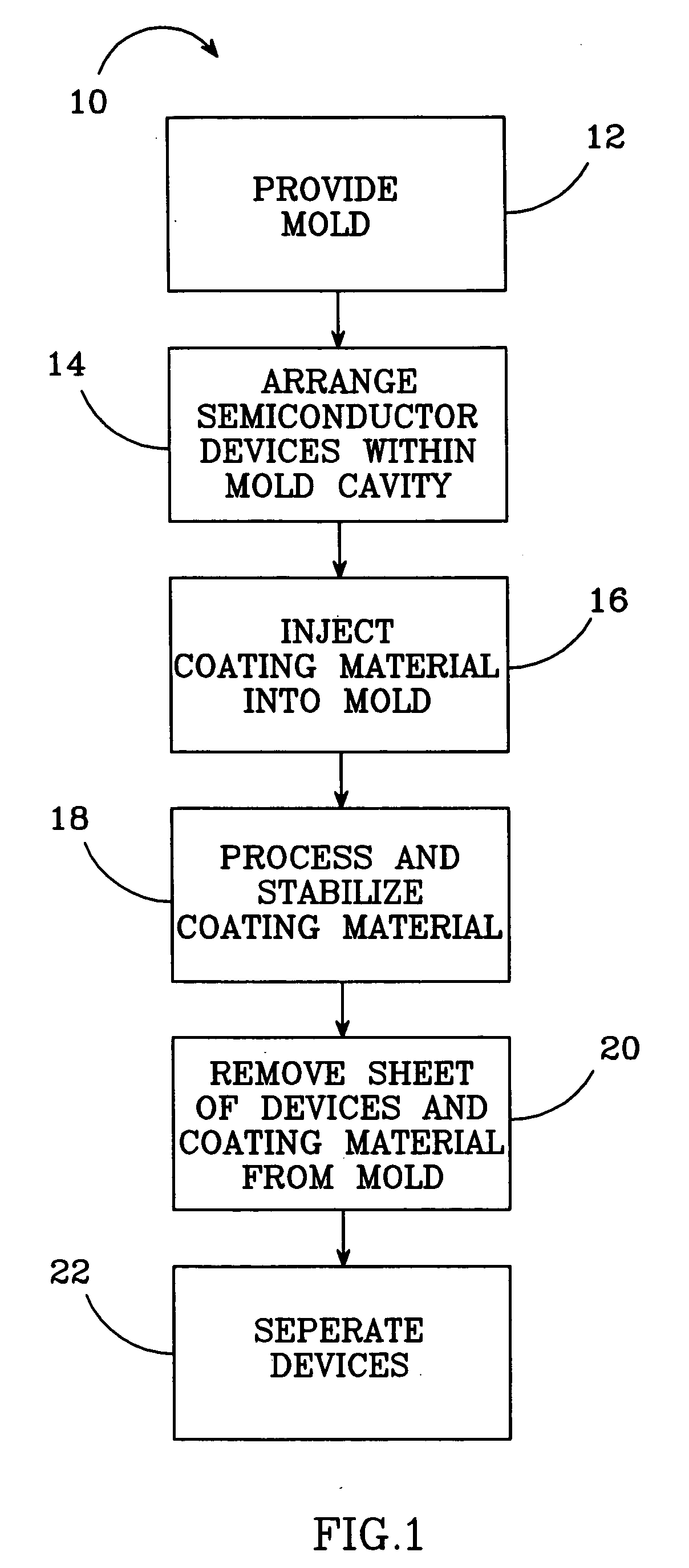
FIG. 1 shows one embodiment of a method 10 for coating semiconductor devices according to the present invention and comprises a first step 12 of providing a mold. A preferred mold comprises a formation cavity that is arranged so that semiconductor devices can be held within it and a coating material can be injected or otherwise introduced into it to cover the devices. The cavity can have many different shapes and is preferably defined by at least upper and lower parallel surfaces. In other embodiments the cavity can be further defined by side surfaces running between the upper and lower surfaces. The different shapes of the formation cavity including, but are not limited to, disk, box or lens shaped. The side surfaces can run around the entire edge of the upper and lower surfaces or can be intermittent.

In step 14, semiconductor devices are arranged within the formation cavity and in the preferred method 10, the devices are precisely arranged in a predetermined pat...


PUM

PropertyMeasurementUnit
adhesiveaaaaaaaaaa
temperatureaaaaaaaaaa
shapeaaaaaaaaaa

Abstract

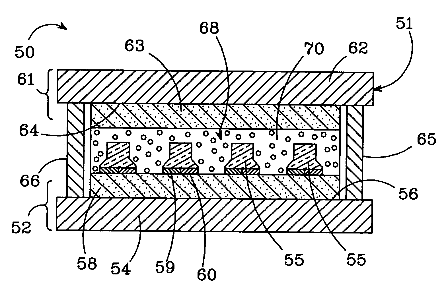
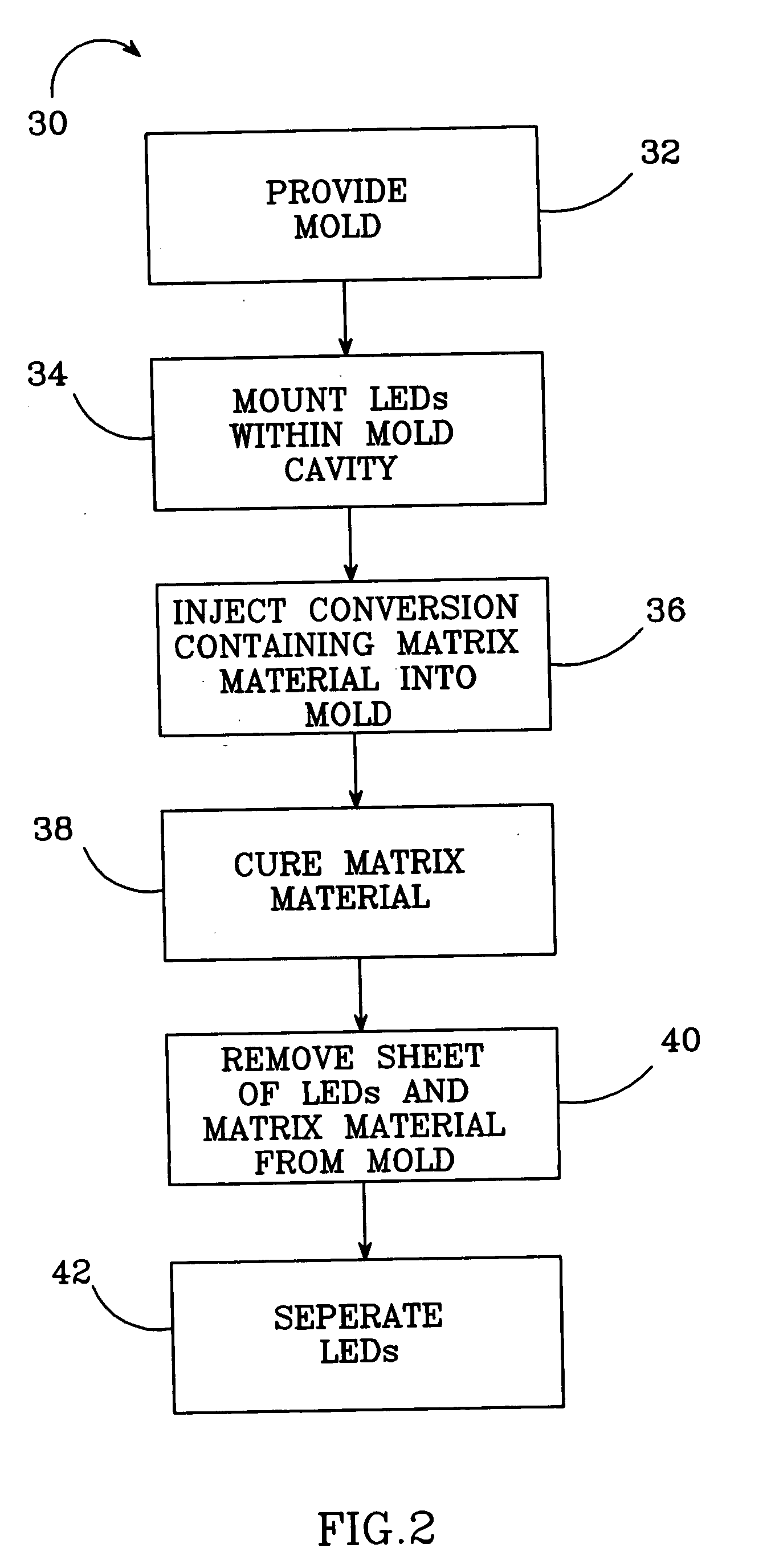
A method and apparatus for coating a plurality of semiconductor devices that is particularly adapted to coating LEDs with a coating material containing conversion particles. One method according to the invention comprises providing a mold with a formation cavity. A plurality of semiconductor devices are mounted within the mold formation cavity and a curable coating material is injected or otherwise introduced into the mold to fill the mold formation cavity and at least partially cover the semiconductor devices. The coating material is cured so that the semiconductor devices are at least partially embedded in the cured coating material. The cured coating material with the embedded semiconductor devices is removed from the formation cavity. The semiconductor devices are separated so that each is at least partially covered by a layer of the cured coating material. One embodiment of an apparatus according to the invention for coating a plurality of semiconductor devices comprises a mold housing having a formation cavity arranged to hold semiconductor devices. The formation cavity is also arranged so that a curable coating material can be injected into and fills the formation cavity to at least partially covering the semiconductor devices.

Description

BACKGROUND OF THE INVENTION 1. Field of the Invention This invention relates to coating of semiconductor devices and more particularly to a method and apparatus for coating light emitting diodes (LEDs) with a matrix material containing one or more light conversion materials. 2. Description of the Related Art LEDs are solid-state devices that convert electric energy to light and they generally comprise an active layer of semiconductor material sandwiched between two oppositely doped layers. When a bias is applied across the doped layers, holes and electrons are injected into the active layer where they recombine to generate light that is emitted omnidirectionally from the active layer and from all surfaces of the LED. Recent advances in LEDs (such as Group III nitride based LEDs) have resulted in highly efficient light sources that surpass the efficiency of filament-based light sources, providing light with equal or greater brightness in relation to input power. One disadvantage...

Claims


Application Information

Patent Timeline
Patent Type & Authority Applications(United States)
IPC IPC(8): H01L21/56H01L33/50
CPCH01L21/565H01L33/50H01L2933/0041H01L27/15H01L33/504H01L2924/12041H01L24/96H01L2924/1815H01L2924/00H01L2924/181H01L2224/2518
Inventor LEUNG, MICHAEL S.TARSA, ERIC J.IBBETSON, JAMES
Owner CREELED INC
Learn More