Electronic part transport device and inspection apparatus using the same
- Summary
- Abstract
- Description
- Claims
- Application Information
AI Technical Summary
Benefits of technology
Problems solved by technology
Method used
Image

Examples
Embodiment Construction
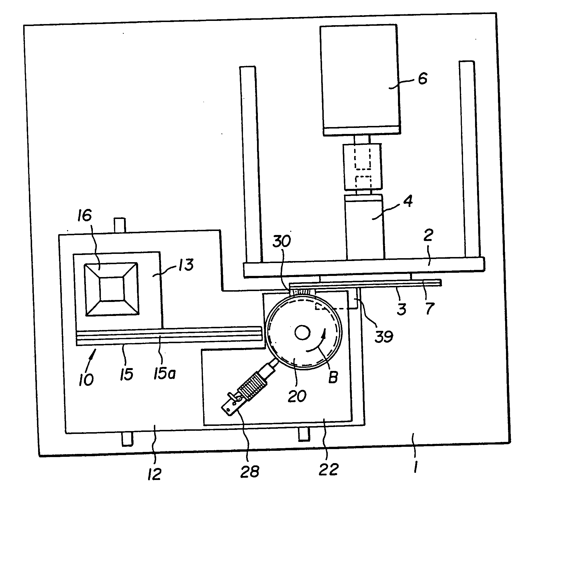
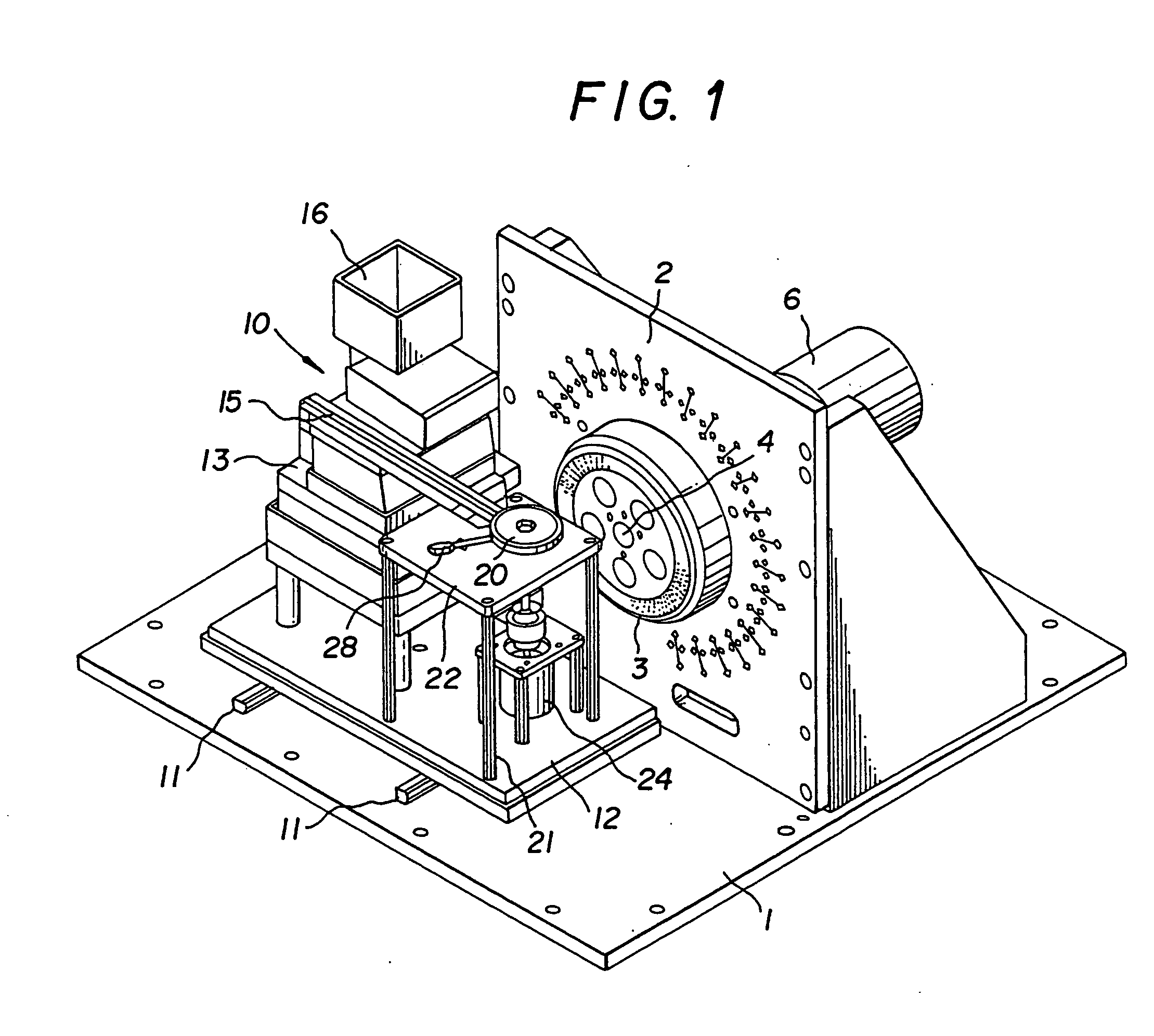
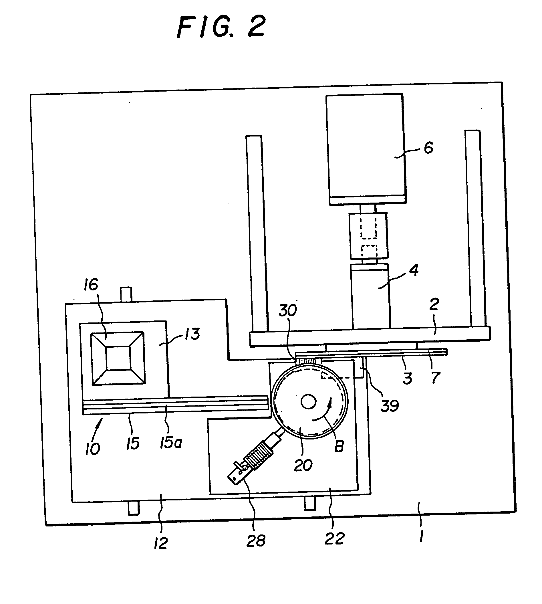
[0047] FIGS. 1 to 8 show an embodiment in which a transport device of the present invention is applied to an inspection apparatus.
[0048] In this embodiment, chip type electronic parts C shaped like a rectangular parallelepiped having a height H, a width W, and a length L (H≈W L>H, and L>W) are used as electronic parts to be inspected, as shown in FIG. 9. Each electronic part C has electrodes Ca and Cb formed at both ends in the longitudinal direction.
[0049] The inspection apparatus comprises a turntable 3 serving as a transport medium, a parts feeder 10 serving as a supply means, a distributing rotor 20 serving as a separating means, and the like, as shown in FIG. 1.
[0050] An upright mounting wall 2 is placed on a base 1 disposed in a fixed section. The turntable 3 is mounted on the mounting wall 2 so as to rotate about a horizontal rotation axis 4. The turntable 3 is made of an insulating material and is integrally shaped like a disk. A plurality of (four in this embodiment) con...
PUM
 Abstract
Description
Claims
Application Information