Folding directional antenna

a directional antenna and antenna array technology, applied in the field of compact configurable antenna apparatus, can solve the problems of multi-path fading, radio frequency signal transmitted from a sender (either a base station or mobile subscriber unit) may encounter interference, fade or dropout of the received signal,

Inactive Publication Date: 2005-03-24
IPR LICENSING INC
View PDF12 Cites 49 Cited by
  • Summary
  • Abstract
  • Description
  • Claims
  • Application Information

AI Technical Summary

Benefits of technology

[0019] The intercell interference problem is exacerbated in CDMA systems since the subscriber units in adjacent cells typically transmit on the same carrier or center frequency. For example, two subscriber units in adjacent cells operating on the same carrier frequency but transmitting to different base stations interfere with each other if both signals are received at one of the base stations. One signal appears as noise relative to the other. The degree of interference and the receiver's ability to detect and demodulate the intended signal is also influenced by the power level at which the subscriber units are operating. If one of the subscriber units is situated at the edge of a cell, it transmits at a higher power level, relative to other units within its cell and the adjacent cell, to reach the intended base station. But, its signal is also received by the unintended base station, i.e., the base station in the adjacent cell. Depending on the relative power level of two same-carrier frequency signals received at the base station, it may not be able to properly differentiate a signal transmitted from within its cell from a signal transmitted from the adjacent cell. A mechanism is required to reduce the subscriber unit antenna's apparent field of view, which can have a marked effect on the operation of the forward link (base to subscriber) by reducing the apparent number of interfering transmissions received at a base station. A similar mechanism is needed for the forward link, to improve the received signal quality at the subscriber unit.
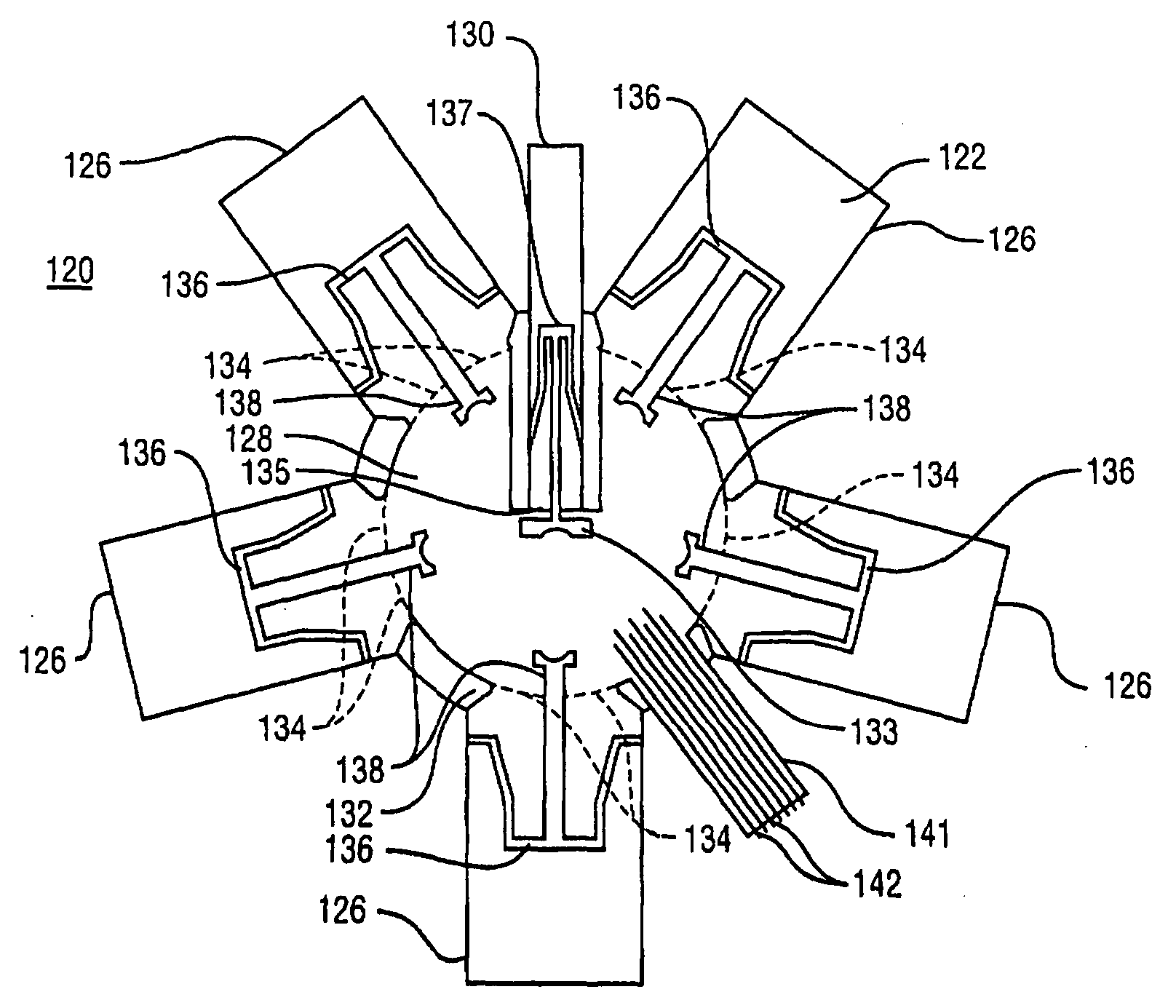
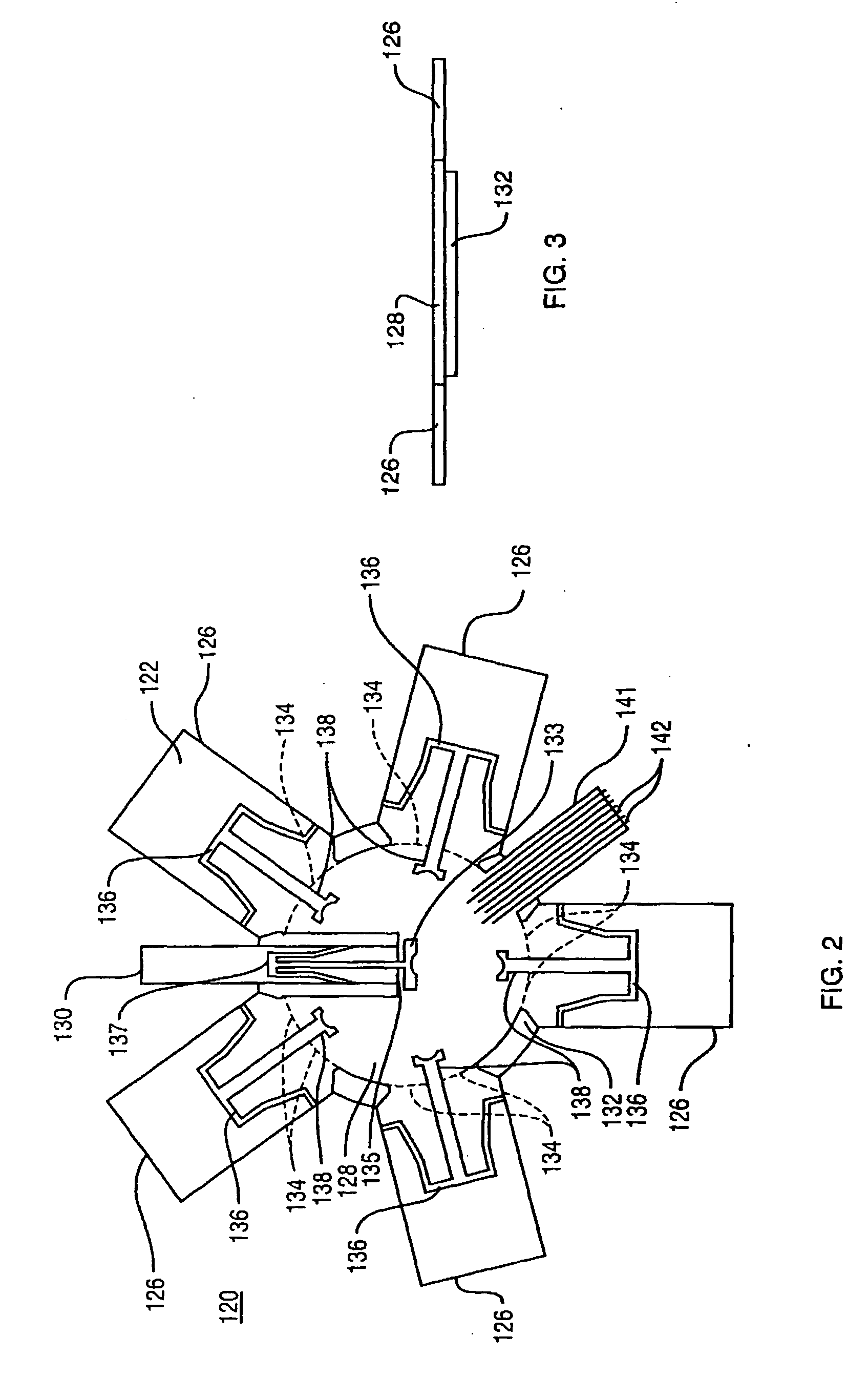
[0022] An integral low profile directional antenna comprises a plurality of elongated antenna arms extending radially from an integral center hub wherein the antenna arms are deformably foldable upwardly into a substantially perpendicular orientation from the center hub to form a directional antenna array. The antenna further comprises a center arm extending from the integral center hub. For storage and transportation, the low profile directional antenna is compactly retractable by deforming the elongated arms into the plane of the integral center hub. The antenna arms and the integral center hub are formed from a homogeneous deformable material, by die cutting, for example, thereby avoiding the need for a separate hinged or pivotal joint for attaching the antenna arms to the integral center hub. The homogeneous deformable material simplifies manufacturing of the antenna and installation into the antenna enclosure.
[0023] In one embodiment, the low profile directional antenna includes five elongated arms and a center arm, all of which are cut from a single sheet of deformable material. Each of these six elements is deformable from an orientation where all elements are in a single plane, into an active or deployed configuration where each element is bent upwardly to form an approximately 90 degree angle with the center hub. Fabricating the antenna from a single sheet avoids all gluing, soldering, etc. operations that are otherwise required to connect the various elements to form the antenna. Also, there are no joints to be created since a deformable material is used. Conductive traces, ground planes, radiating structures, vias, etc. are disposed on the deformable material or on parallel layers bonded above or below the deformable material. These conductive components are produced on the deformable material by an etching or printing process. The fabrication parts count is low (there is only one piece part) and thus labor costs are minimized through fabrication of all the antenna elements from the single part.

Problems solved by technology

One such problem is called multipath fading.
In multipath fading, a radio frequency signal transmitted from a sender (either a base station or mobile subscriber unit) may encounter interference in route to the intended receiver.
As a result, the original and reflected signals may partially or completely cancel each other out (destructive interference), resulting in fading or dropouts in the received signal.
Single element antennas are highly susceptible to multipath fading.
A single element antenna cannot determine the direction from which a transmitted signal is sent and therefore cannot be tuned to more accurately detect and receive a transmitted signal.
The dual element antenna described in the aforementioned patent reference is also susceptible to multipath fading due to the symmetrical and opposing nature of the hemispherical lobes of the antenna pattern.
That is, if the transmitted signal reflects from an object beyond or behind the received antenna and is then reflected back to the intended receiver from the opposite direction as the signal received directly from the source, then a phase difference in the two signals creates destructive interference due to multipath fading.
Another problem present in cellular communication systems is inter-cell signal interference.
Intercell interference occurs when a mobile subscriber unit near the edge of one cell transmits a signal that crosses over the edge into a neighboring cell and interferes with communications taking place within the neighboring cell.
Typically, signals in neighboring cells on the same or closely-spaced frequencies cause intercell interference.
The problem of intercell interference is compounded by the fact that subscriber units near the edge of a cell typically transmit at higher power levels so that their transmitted signal can be effectively received by the intended base station located at the cell center.
Also, the signal from another mobile subscriber unit located beyond or behind the intended receiver may arrive at the base station at the same power level, representing additional interference.
The intercell interference problem is exacerbated in CDMA systems since the subscriber units in adjacent cells typically transmit on the same carrier or center frequency.
For example, two subscriber units in adjacent cells operating on the same carrier frequency but transmitting to different base stations interfere with each other if both signals are received at one of the base stations.
Depending on the relative power level of two same-carrier frequency signals received at the base station, it may not be able to properly differentiate a signal transmitted from within its cell from a signal transmitted from the adjacent cell.

Method used


Image

  • Folding directional antenna
  • Folding directional antenna
  • Folding directional antenna

Examples


Embodiment Construction

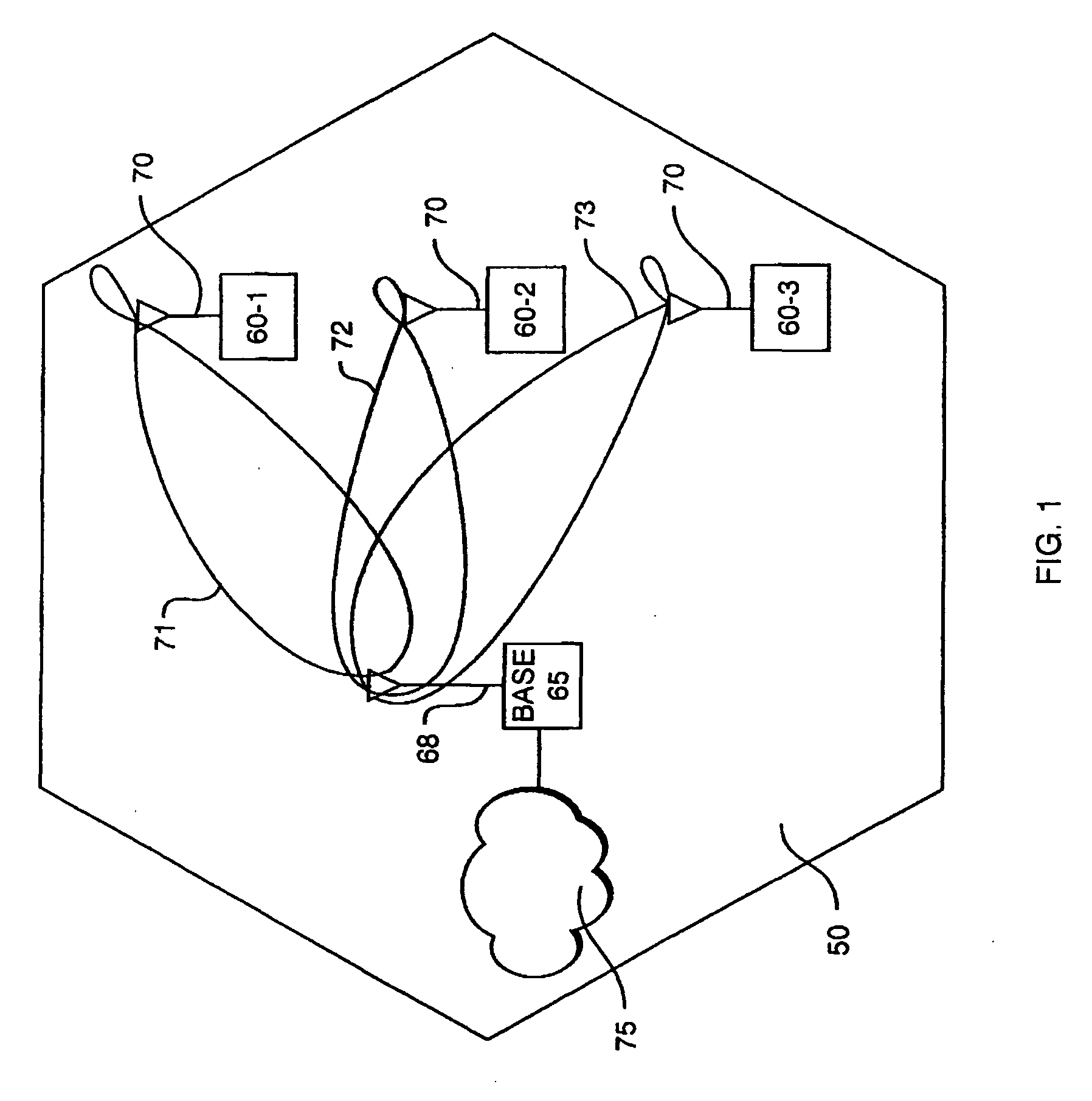
[0034]FIG. 1 illustrates one cell 50 of a typical CDMA cellular communication system. The cell 50 represents a geographical area in which mobile subscriber units 60-1 through 60-3 communicate with a base station 65. Each subscriber unit 60 is equipped with an antenna 70, which may be constructed according to the present invention. The subscriber units 60 are provided with wireless data and / or voice services by the system operator, through which devices such as, for example, laptop computers, portable computers, personal digital assistants (PDAs) or the like can be connected to the base station 65 (including the antenna 68) to a network 75, which can be the public switched telephone network (PSTN), a packet switched computer network (such as the Internet) a public data network or a private network. The base station 65 communicates with the network 75 over any number of different available communications protocols such as primary rate ISDN, or other LAPD based protocols such as IS-634...


PUM


Abstract

An antenna array formed on a deformable dielectric material or substrate includes a center element and plurality of radial elements extending from a center hub. In the operative mode, the radial elements are folded upwardly into an approximately vertical position, with the center element at the center of the hub and the radial elements circumferentially surrounding the center element. In one embodiment the center element serves an active element of the antenna array and the radial elements are controllable in a directive or reflective state to effect a directive beam pattern from the antenna array. When not in use, the antenna elements are deformed into a plane and can therefore be integrated into a housing for compact storage. In a phased array embodiment, the center element is absent and the plurality of radial elements, are controllable to steer the antenna beam.

Description

RELATED APPLICATION [0001] This application is a continuation-in-part of a co-pending U.S. application Ser. No. 09 / 852,598 filed May 10, 2001. The entire teachings of the above application are incorporated herein by reference.FIELD OF THE INVENTION [0002] This invention relates to mobile or portable cellular communication systems, and more particularly to a compact configurable antenna apparatus for use with mobile or portable subscriber units. BACKGROUND OF THE INVENTION [0003] Code division multiple access (CDMA) communication systems provide wireless communications between a base station and one or more mobile or portable subscriber units. The base station is typically a computer-controlled set of transceivers that are interconnected to a land-based public switched telephone network (PSTN). The base station further includes an antenna apparatus for sending forward link radio frequency signals to the mobile subscriber units and for receiving reverse link radio frequency signals tr...

Claims


Application Information

Patent Timeline
Patent Type & Authority Applications(United States)
IPC IPC(8): H01Q1/08H01Q1/24H01Q1/38H01Q3/01H01Q3/20H01Q3/24H01Q3/26H01Q19/32H01Q21/06H01Q21/20
CPCH01Q1/08H01Q1/084H01Q1/085H01Q1/241H01Q1/242H01Q1/38H01Q21/20H01Q3/20H01Q3/24H01Q3/26H01Q19/32H01Q21/061H01Q3/01
Inventor CHIANG, BINGPALMER, WILLIAM R.GOTHARD, GRIFFIN K.SNYDER, CHRISTOPHER A.
Owner IPR LICENSING INC
Why Eureka
Try Eureka