Apparatus for measuring two-dimensional displacement

a two-dimensional displacement and apparatus technology, applied in the field of apparatus for measuring two-dimensional displacement, can solve the problems of increasing the risk of personnel outflow, and difficulty in meeting the requirement for being used in high-precision systems. , to achieve the effect of easy to obtain periodic wave interference signals

Active Publication Date: 2005-03-24
IND TECH RES INST
View PDF6 Cites 5 Cited by
  • Summary
  • Abstract
  • Description
  • Claims
  • Application Information

AI Technical Summary

Benefits of technology

[0008] An object of the present invention is to provide a two-dimensional displacement measuring apparatus so as to easily obtain periodic wave interference signals formed relative to a displacement of two-dimensional diffraction device.
[0009] A further object of the present invention is to provide a two-dimensional displacement measuring apparatus so as to have tolerance of high alignment error, low manufacturing cost and high product yield.

Problems solved by technology

However, the aforesaid two-dimensional displacement measuring module is suitable for the low-precision systems only, and has difficulty in meeting the requirement for being used in the high-precision systems.
For example, there are problems in orthogonality precision between the two axes and orthogonality between a beam splitter / mirror and the optical path of an interferometer.
Therefore, costs for education and training of staff as well as risk of personnel outflow are increased.
Although there are currently several methods for improving the two-dimensional displacement measuring apparatus, a number of defects in efficiency exist.
U.S. Pat. No. 5,424,833 also discloses a two-dimensional displacement measuring apparatus in which beams are diffracted three times with the undesired result that the luminance is poor, thus demanding finely manufactured components and assembly of the components to be involved in the system.
U.S. Pat. No. 5,530,543 discloses a two-dimensional displacement measuring apparatus in which self-compensating function for errors are absent so that outputting signals are likely to be unstable in practice.
It is therefore difficult for the second diffracted beam to be taken out individually.

Method used


Image

  • Apparatus for measuring two-dimensional displacement
  • Apparatus for measuring two-dimensional displacement
  • Apparatus for measuring two-dimensional displacement

Examples


first embodiment

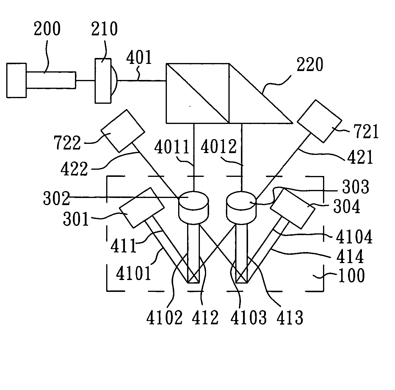
[0029]FIG. 5 schematically illustrates the aforesaid interference optical dephasing module 721. With reference to FIGS. 2 and 5 for the following description, because the second diffracted beam 421 reflected by the two-dimensional diffraction unit 100 contains information about displacement in the X direction, the second diffracted beam 421 is dephased by means of the interference optical dephasing module 721 to obtain periodic wave signals of displacement information in the X direction so that a two-dimensional displacement is measured based on the periodic wave signals. The interference optical dephasing module 721 comprises a beam splitter 7211 and polarisers 731, 732, the polarisers 731, 732 being disposed on the optical paths formed by the beam splitter 7211 respectively with an angle of 45° between the optical axes thereof. After the second diffracted beam 421 enters the interference optical dephasing module 721, two signal beams 4211, 4212, which are split by means of the bea...

second embodiment

[0030]FIG. 6 schematically illustrates the interference optical dephasing module 721. With reference to FIGS. 2 and 6 for the following description, the interference optical dephasing module 721 comprises beam splitters 7222, 7223, 7224 and polarisers 733, 734,735736 having an angle of 45° between the optical axes thereof. After the second diffracted beam 421 enters the interference optical dephasing module 721, two signal beams 4213, 4214 are split by means of the beam splitter 7222. Further, the signal beam 4213 is split by means of the beam splitter 7223 to form two signal beams 4215, 4216 while the signal beam 4214 is split by means of the beam splitter 7224 to form two signal beams 4217, 4218. Accordingly, the four signal beams 4215, 4216, 4217, 4218 are formed after the second diffracted beam 421 enters the interference optical dephasing module 721, passing through the polarisers 733, 734, 735, 736, respectively.

[0031] In sum, the second-order diffracted beams generated as a r...


PUM


Abstract

An apparatus for measuring a two-dimensional displacement is disclosed and includes a laser light source, a collimator lens, a beam splitter, a plurality of staggered conjugate optic lens and a plurality of interference optical dephasing modules. The laser light source provides a laser light incident on the collimator lens to generate collimated laser beams. Each of the collimated laser beams are incident on the beam splitter to be separated into two incident beams and incident on a two-dimensional diffraction unit to generate a plurality of first diffracted beams and a plurality of second-order diffracted beams. The staggered conjugate optic lens are used to reflect the first diffracted beams so that the first diffracted beams return to the two-dimensional diffraction unit to generate a plurality of second diffracted beams where the second diffracted beams and the second-order diffracted beams generated as a result of the first diffraction of the beams stagger.

Description

BACKGROUND OF THE INVENTION [0001] 1. Field of the Invention [0002] The present invention relates to an apparatus for measuring a displacement, and more particularly, to an apparatus for measuring a two-dimensional displacement. [0003] 2. Description of Related Art [0004] The conventional two-dimensional displacement measuring module consists of two linear displacement measuring modules disposed orthogonally with respect to each other, the linear displacement measuring module being a common apparatus such as an optical linear scale encoder, a magnetic scale encoder, a linear variable differential transformer (LVDT) or a laser interferometer. However, the aforesaid two-dimensional displacement measuring module is suitable for the low-precision systems only, and has difficulty in meeting the requirement for being used in the high-precision systems. For example, there are problems in orthogonality precision between the two axes and orthogonality between a beam splitter / mirror and the o...

Claims


Application Information

Patent Timeline
Patent Type & Authority Applications(United States)
IPC IPC(8): G01B9/02
CPCG01B9/02G01B9/02027G01B2290/70G01B2290/30
Inventor KAO, CHING-FENCHANG, CHUNG-CHULIN, CHING-FANG
Owner IND TECH RES INST
Why Eureka
Try Eureka