Rotating disk storage device

a technology of rotating disks and storage devices, which is applied in the direction of head support, instruments, magnetic recording, etc., can solve the problems of increasing the difficulty of obtaining a high torque from a vcm, the number of turns of voice coils, and the influence of the thickness of voice coil magnets on the magnetic field strength of a yoke gap, etc., to achieve the effect of simple structur

Inactive Publication Date: 2005-03-24
HITACHI GLOBAL STORAGE TECH NETHERLANDS BV
View PDF7 Cites 10 Cited by
  • Summary
  • Abstract
  • Description
  • Claims
  • Application Information

AI Technical Summary

Benefits of technology

[0022] According to embodiments of the present invention, it is possible to provide a rotating disk storage device having a function of reliably retracting an actuator head suspension assembly into a retraction area even when the power supply is suddenly interrupted during operation. Moreover, it is possible to pr

Problems solved by technology

If a spindle motor holding the magnetic disk is rotated with the head/slider being attracted, a phenomenon of sticktion occurs, which may make a flaw in the slider and on the surface of the magnetic disk or may hinder a motor from starting.
In the event that the power supply is suddenly interrupted while the head/slider accesses the recording surface of the magnetic disk, no energy is available to drive an actuator assembly into the retraction area.
With the progress of the miniaturization of magnetic disk drives, the number of turns of a voice coil, and a thickness of a voice coil magnet influencing on magnetic field strength of a yoke gap, are limited by spatial limitations.
Therefore, it has become increasingly difficult to obtain a high torque from a VCM.
Moreover, there are many limitations in the amount of back electromotive force of a spindle motor and the amount of an electric charge to be accumulated in a capacitor.
Accordingly, in the case of the small-size magnetic disk drive, it is more difficult to reserve the energy for securely retracting a head/slider into a ramp in the event of interruption of the power supply, an

Method used


Image

  • Rotating disk storage device
  • Rotating disk storage device
  • Rotating disk storage device

Examples


Embodiment Construction

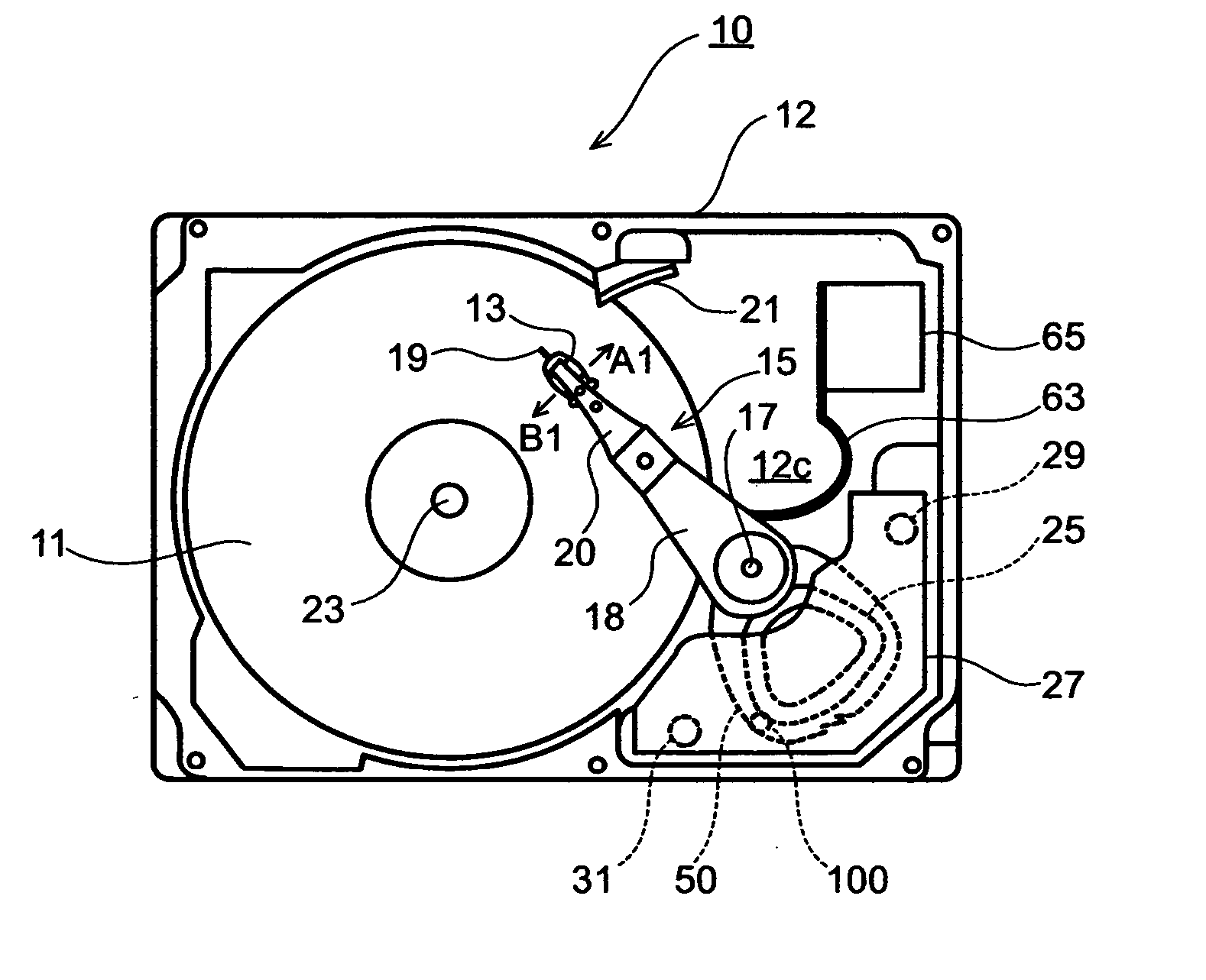
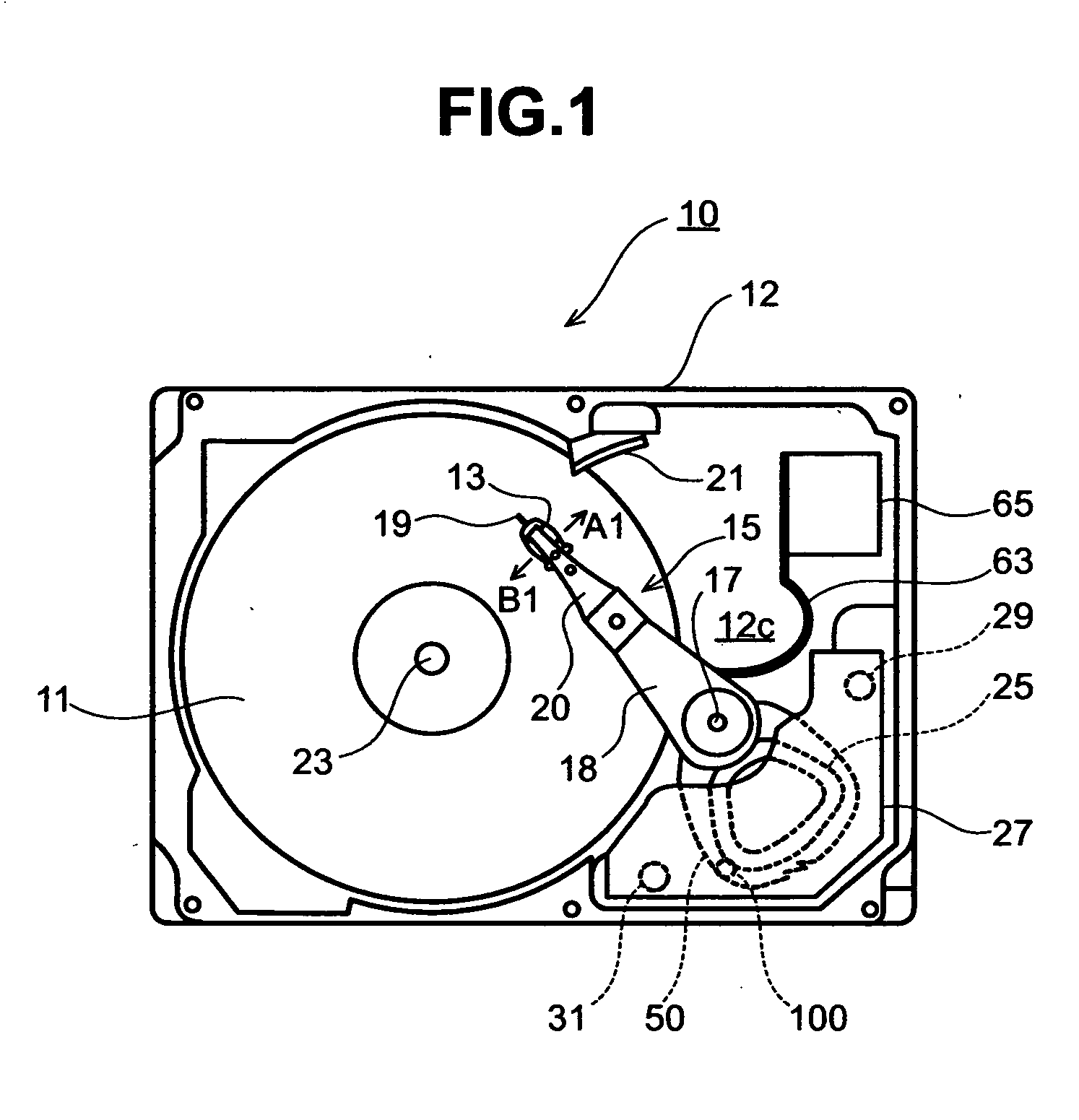
[0032] A magnetic disk drive according to an embodiment of the present invention will be described with reference to FIGS. 1 through 3. FIG. 1 is a schematic plan view of a magnetic disk drive 10. FIG. 2(A) is a side view of a ramp 21; and FIG. 2(B) is a perspective view of the ramp 21. FIG. 3 is an exploded perspective view of the magnetic disk drive 10. The magnetic disk drive 10 is housed in a casing body 12 to which a casing lid 12b (refer to FIG. 3) is mounted. The casing body 12 is mainly constituted of a base 12c for providing stored parts with mounting surfaces, and side walls to which the casing lid 12b is mounted. The casing body 12 is formed by pressing a metal flat board.

[0033] A disc-shaped magnetic disk 11 has recording surfaces on both sides, each of which is covered with a magnetic layer formed on its surface. The magnetic disk 11 is attached to a hub that is coupled to a spindle motor provided on the lower part. The magnetic disk 11 rotates about a spindle shaft 23...


PUM


Abstract

Embodiments of the present invention provide a rotating disk storage device having a mechanism to reliably retract an actuator into a retraction area in the event that the power supply is suddenly interrupted. A bias chip is embedded in a coil support that supports the voice coil. When a head stays in an access area, the bias chip is away from an end of the voice coil magnet. Therefore, no influence of the magnetic leakage flux is exerted on the bias chip. When the head is in a retraction area, the bias chip is attracted under the influence of the magnetic leakage flux of the voice coil magnet, which thereby produces bias torque causing an actuator to pivotally move in a retraction direction. Accordingly, the bias torque can be utilized as energy for retracting the actuator immediately after power shutdown.

Description

BACKGROUND OF THE INVENTION [0001] The present invention relates to a rotating disk storage device such as a magnetic disk drive and a magneto-optic disk drive, and more particularly to a mechanism for giving supplementary force to a driving mechanism of an actuator. [0002] A magnetic disk drive pivotally moves a head / slider, which is supported by an actuator assembly, approximately in a radial direction of a magnetic disk while floating the head / slider with a slight gap being kept on a recording surface of a rotating magnetic disk, and thereby reads and writes data. A load beam used to support the head / slider generates a pressing load in the form of a pressure in a direction in which the head / slider is pressed on the recording surface of the magnetic disk. This pressing load is balanced with the buoyancy which an air bearing surface of a slider receives from airflow occurring on a surface of the magnetic disk. As a result, a given gap is kept between the air bearing surface and the...

Claims


Application Information

Patent Timeline
IPC IPC(8): G11B5/54G11B21/12G11B21/22
CPCG11B5/54G11B21/22G11B21/12
Inventor MATSUMURA, SATOSHIKUROKI, KENJIKITAHORI, HIROKIKIMURA, SHINICHI
Owner HITACHI GLOBAL STORAGE TECH NETHERLANDS BV
Why Eureka
Try Eureka