Method for transmitting digital image signal, digital image transmitting device, digital image sending device and digital image receiver

a digital image and transmission method technology, applied in the field of digital image transmission and reception, can solve the problems of inconvenient instalment and use of communication devices, complex and costly complete system using this communication system, and achieve the effect of increasing costs and high quality

Inactive Publication Date: 2005-03-24
SEIKO EPSON CORP
View PDF8 Cites 79 Cited by
  • Summary
  • Abstract
  • Description
  • Claims
  • Application Information

AI Technical Summary

Benefits of technology

[0063] Since the digital image signal is converted into the serial digital image signal, only a single cable for receiving the optical signal is needed. Thereby, by optical communi

Problems solved by technology

However, digital transmission standards by metal wire transmission in high frequencies from several hundred MHz to several GHz have a problem in that image quality of the middle resolution class (XGA; 1024×768 pixel) can be communicated only up to around 10 m and image quality of the high resolution class (HDTV; 1920×1080 pixels) can be communicated only up to around 5 m.
Therefore, a complete system using this communication system is complex and costly due to the number of required components.
Also, because of the number of components, the communication device is inconvenient to instal and use.
In such high frequenc

Method used


Image

  • Method for transmitting digital image signal, digital image transmitting device, digital image sending device and digital image receiver
  • Method for transmitting digital image signal, digital image transmitting device, digital image sending device and digital image receiver
  • Method for transmitting digital image signal, digital image transmitting device, digital image sending device and digital image receiver

Examples


first embodiment

[0092] First, a first embodiment is described.

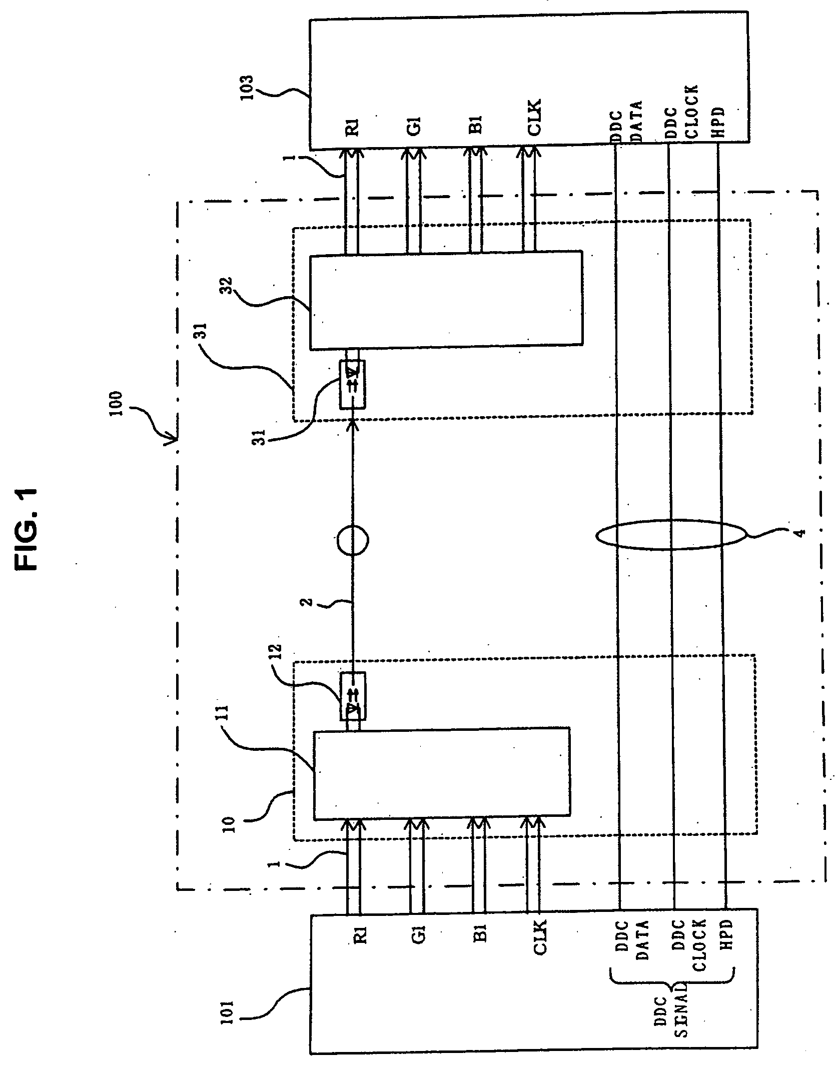
[0093]FIG. 1 shows an outline block diagram illustrating an example of a digital image communication device according to the present invention.

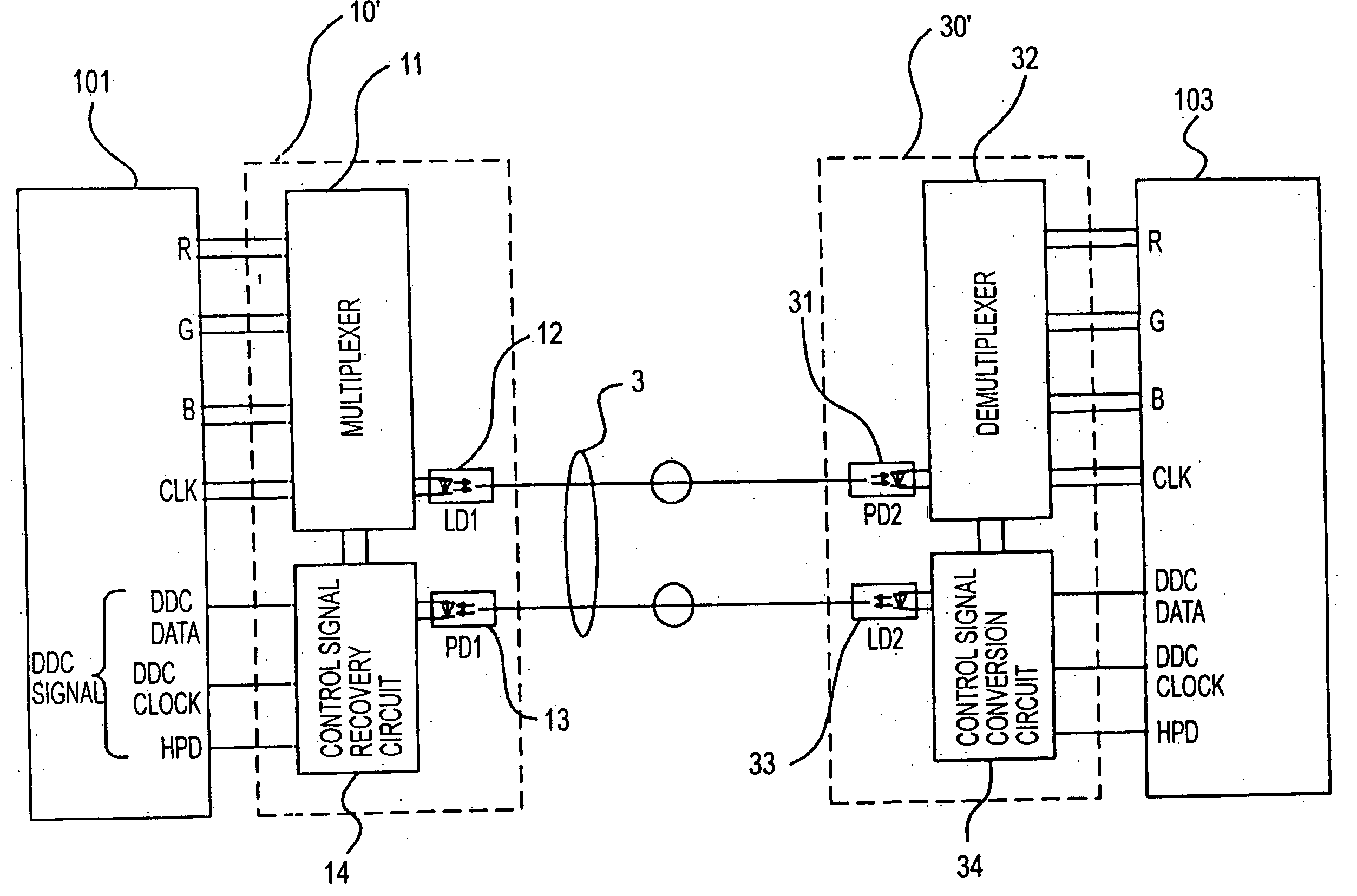
[0094] As shown in FIG. 1, the digital image communication device 100 includes a transmission section 10 arranged in the vicinity of digital image output equipment 101 outputting a digital image signal, a reception section 30 arranged in the vicinity of a digital image input equipment 103 receiving the digital image signal of such as a display device, and a fiber optic cable 2 connecting the transmission section 10 and the reception section 30.

[0095] The digital image output equipment 101 and the digital image input equipment 103 have TMDS1 link type DVI standard interfaces as their respective interfaces. The digital image output equipment 101 and the transmission section 10, and the digital image input equipment 103 and the reception section 30 are respectively connected by DVI cables 1 complyi...

second embodiment

[0124] Next, a second embodiment according to the present invention is described.

[0125] Since the second embodiment is similar to the first embodiment except for the structures of the transmission section 10 and the reception section 30, identical reference numerals are given to identical parts, and a detailed description is omitted.

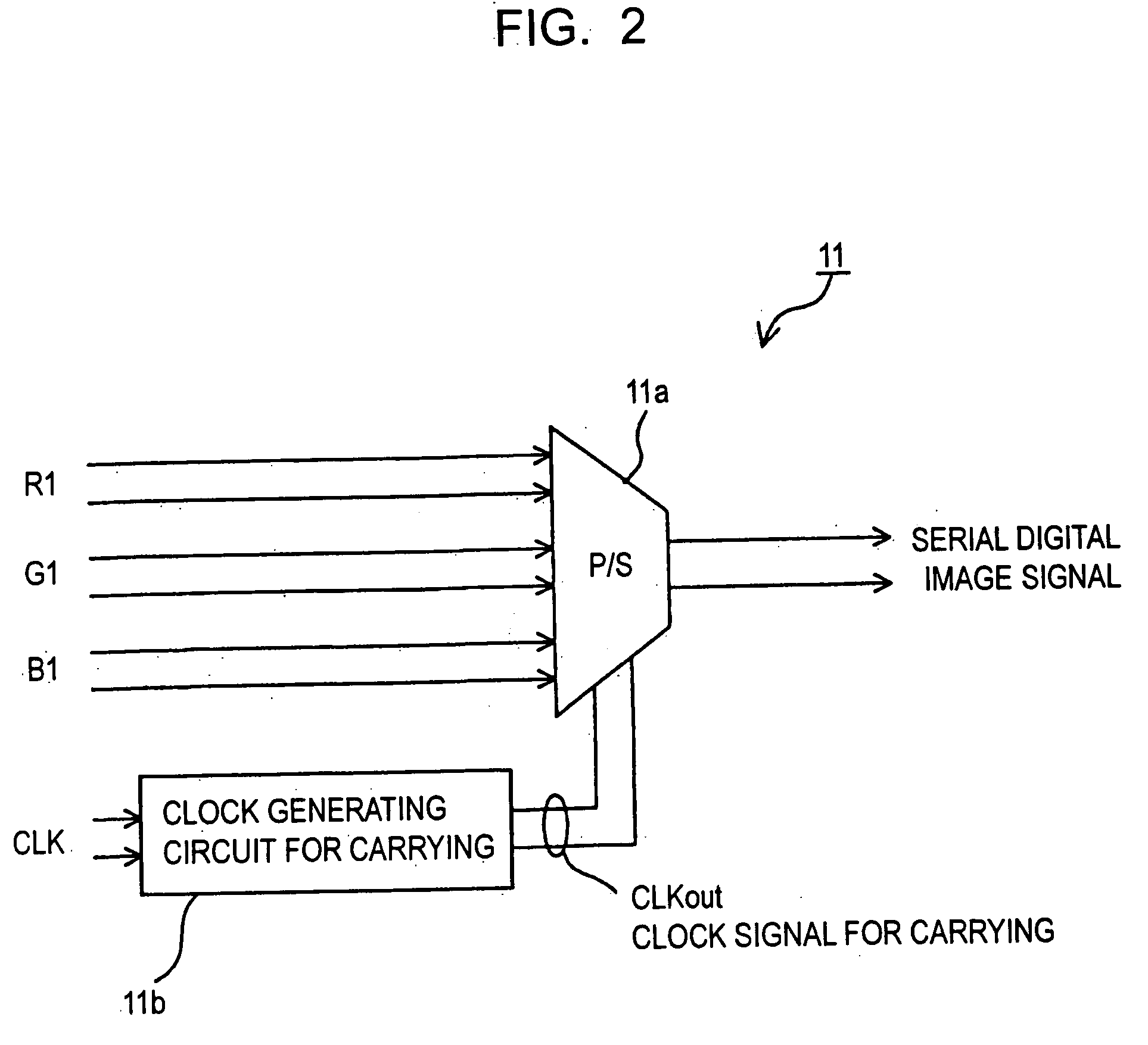
[0126] In the second embodiment, a multiplexer 11 of a transmission section 10 comprises, as shown in FIG. 8 and similar to the first embodiment, a parallel / serial conversion circuit 11a receiving RGB image signals in parallel and converting the RGB image signals into a serial signal on the basis of a clock signal “CLKout for carrying”, a “clock generating circuit 11b for carrying” generating the clock signal CLKout for carrying by multiplying a reference clock signal CLK by a predetermined number, and an encoding circuit 51 encoding a serial digital image signal output from the parallel / serial conversion circuit 11a.

[0127] A demultiplexer 32 of a rece...

third embodiment

[0142] Next, a third embodiment according to the present invention is described.

[0143] Since the third embodiment is similar to the first embodiment except for the structures of the transmission section 10 and the reception section 30, identical reference numerals are given to identical parts, and a detailed description is omitted.

[0144] In the third embodiment, a multiplexer 11 of a transmission section 10 comprises, as shown in FIG. 12 and similar to the first embodiment, a parallel / serial conversion circuit 11a receiving RGB image signals in parallel and converting the RGB image signals into a serial digital signal on the basis of a clock signal “CLKout for carrying”, a “clock generating circuit 11b for carrying” generating the clock signal CLKout for carrying by multiplying a reference clock signal CLK by a predetermined number, and an error code addition circuit 55 adding an error code (bit for checking) to a serial digital image signal converted by the parallel / serial convers...


PUM


Abstract

A multiplexer of a transmission section generates a clock signal by multiplying a reference clock signal of a digital image signal by a predetermined number ‘K’. A parallel digital image signal is converted into a serial digital signal on the basis of the clock signal, and the serial digital signal is converted into an optical signal in an optical transmission section for transmitting. A demultiplexer extracts a reception clock signal from a serial digital reception signal which is converted into an electric signal in an optical reception section of a reception section, the serial digital reception signal is converted into a parallel signal and a signal corresponding to the parallel digital image signal on the basis of the reception clock signal, and a clock signal corresponding to the reference clock signal is recovered by multiplying the reception clock signal by ‘1/K’.

Description

RELATED APPLICATIONS [0001] This application claims priority to Japanese Patent Application Nos. 2003-289037 filed Aug. 7, 2003 and 2004-056186 filed Mar. 1, 2004 which are hereby expressly incorporated by reference herein in their entirety. BACKGROUND [0002] 1. Technical Field [0003] The present invention relates to a method for communicating (transmitting & receiving) digital image signal, a digital image communication (transmission & reception) device, a digital image transmitter and a digital image receiver enabling long distance communication. [0004] 2. Background Art [0005] In the past, for example, as a method for sending a digital image signal to a display device such as an LCD monitor, a projector, etc. from a digital image reproducing device such as a computer, video image reproducing equipment, etc., metal wire transmission by coaxial cable was widely used. [0006] As an interface for sending the digital image signal, the DVI (Digital Visual Interface) standard is used, an...

Claims


Application Information

Patent Timeline
IPC IPC(8): H04N7/22H04B10/00H04B10/2507H04B10/556H04L7/04H04L25/14H04N21/436H04N21/647
CPCH04L25/14
Inventor IMAI, NOBUYUKI
Owner SEIKO EPSON CORP
Why Eureka
Try Eureka