
Method and/or system for identifying fluorescent, luminescent and/or absorbing substances on and/or in sample carriers

a technology of fluorescent, luminescent and/or absorbing substances, applied in the direction of biological instruments and processes, instruments, and analysis by subjecting materials to chemical reactions, can solve the problems of reducing detection sensitivity, time-consuming measurement of more than two wavelength bands, and very small intensity of detected signals

Inactive Publication Date: 2005-03-24
CARL ZEISS JENA GMBH
View PDF6 Cites 17 Cited by
  • Summary
  • Abstract
  • Description
  • Claims
  • Application Information

AI Technical Summary

Benefits of technology

The method according to the invention has the following advantages over previous methods: The quantity of dye signatures that may be used simultaneously, i.e., the quantity of characteristics, for example, of cells that can be investigated simultaneously, can be increased by means of the method according to the invention. When the spectral signatures of the individual dyes overlap extensively, the wavelength range must be limited, according to the prior art, for separate detection of the fluorescence signals of individual dyes. This reduces the sensitivity of detection, i.e., increases the noise of the detectors, because greater amplification must be used. This is avoided by the method according to the invention. Further, nonspecific fluorescence signals, autofluorescence and fluorescence of the measuring device can be separated.

Problems solved by technology

The disadvantage in the methods mentioned above consists in that the number of selectable detection bands and their bandwidth is predetermined by the filter being used and measurement of more than two wavelength bands is time-consuming.
As a result, the intensity of the detected signal is very small due to the small bandwidth.
This reduces the sensitivity of detection, i.e., increases the noise of the detectors, because greater amplification must be used.

Method used


Image

  • Method and/or system for identifying fluorescent, luminescent and/or absorbing substances on and/or in sample carriers
  • Method and/or system for identifying fluorescent, luminescent and/or absorbing substances on and/or in sample carriers
  • Method and/or system for identifying fluorescent, luminescent and/or absorbing substances on and/or in sample carriers

Examples


embodiment form

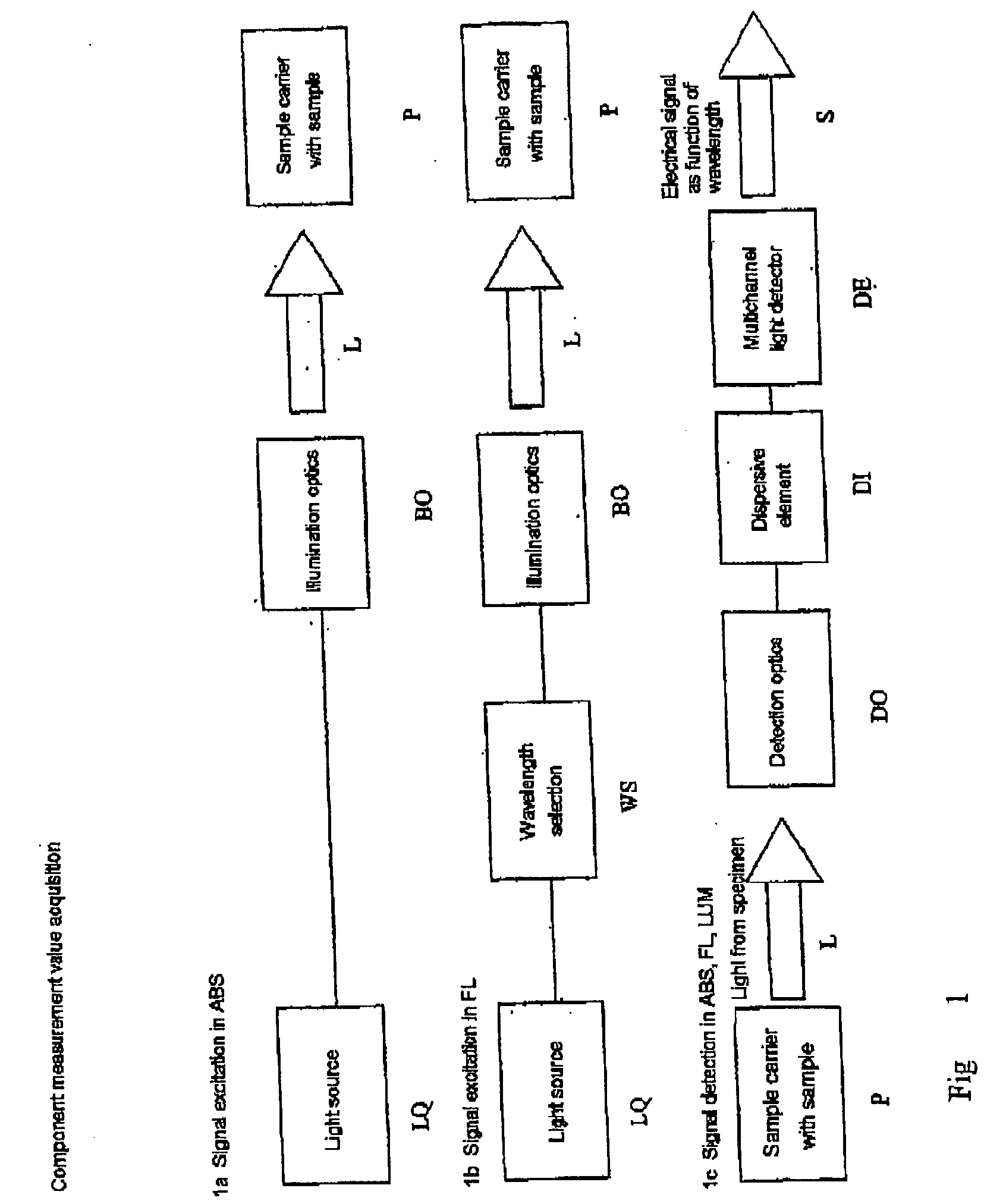
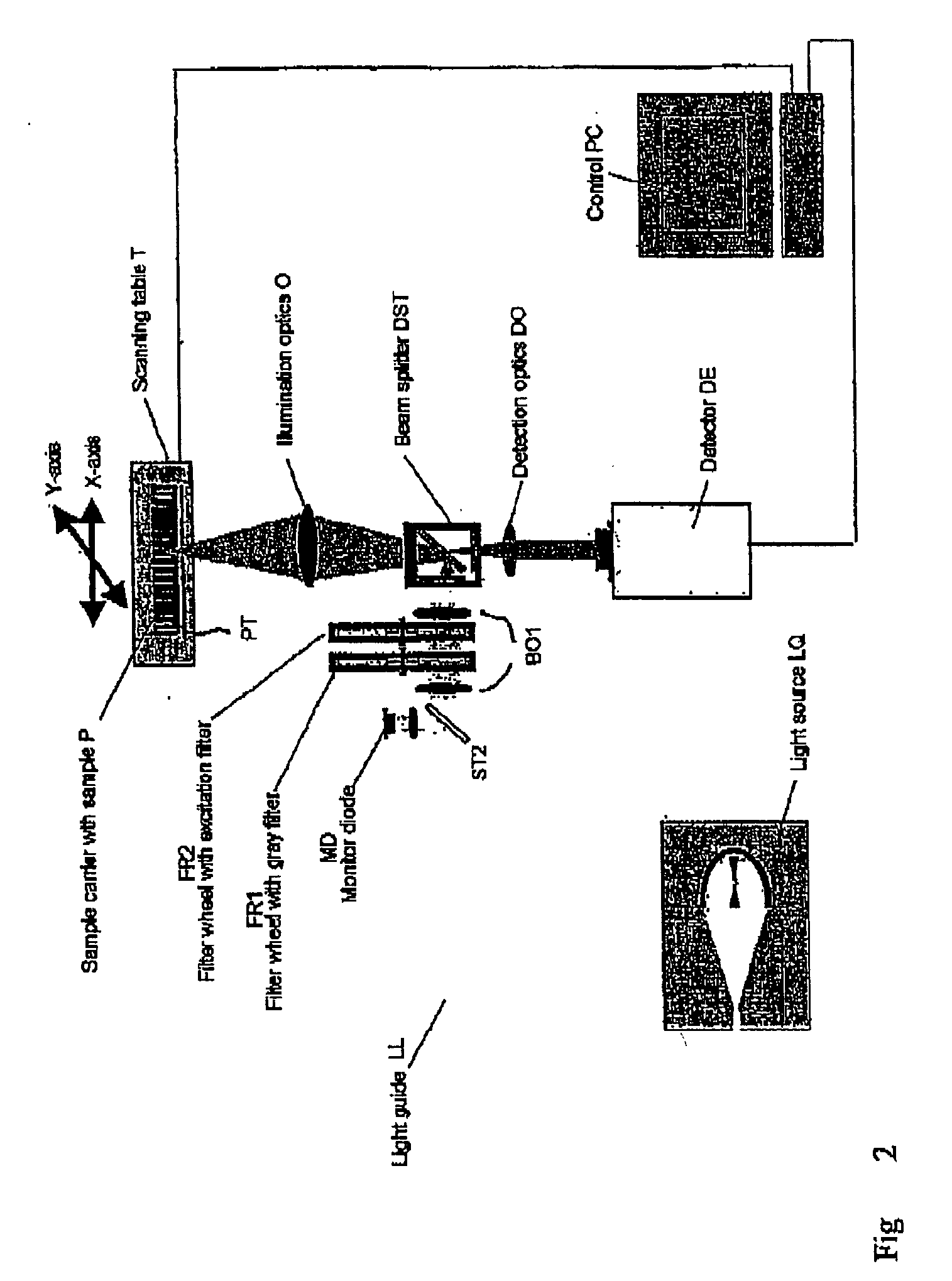
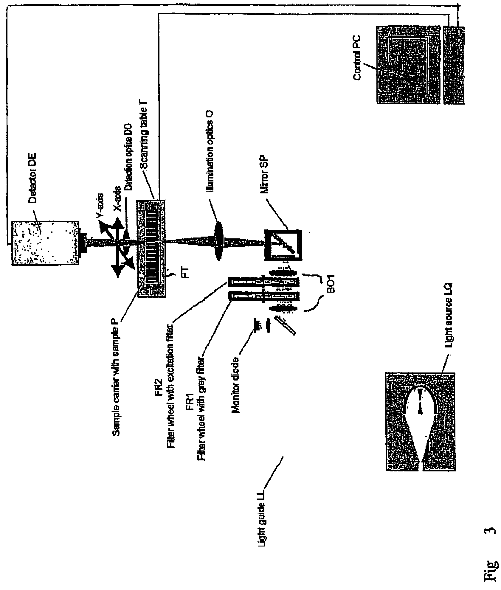
A possible embodiment form of the optical beam path of the detector unit shown in the block diagram in FIG. 1 is illustrated in FIG. 4. The construction is essentially a Czerny Turner construction. The light L of the sample is focused with the detection optics DO1 which receives the parallel light of the DO in FIGS. 2, 3. A baffle or stray-light diaphragm SB can be used, but is not absolutely necessary.

The first imaging mirror M2 collimates the fluorescent light. Subsequently, the light strikes a line grating G, for example, a grating with a line number of 651 lines per mm. The grating bends the light in different directions corresponding to its wavelength. The second imaging mirror M1 focuses the individual spectrally split wavelength components on the corresponding channels of the line detector DE. The use of a secondary electron multiplier array by Hamamatsu H7260 is especially advantageous. The detector has 32 channels and high sensitivity. The free spectral region of the embod...


PUM

PropertyMeasurementUnit
Ratioaaaaaaaaaa
Fluorescenceaaaaaaaaaa
Spectrumaaaaaaaaaa

Abstract

Method and / or arrangement for identifying fluorescing, luminescing and / or absorbing substances on and / or in sample carriers, particularly with high sample throughput in sample screening and / or in diagnostics, preferably in the analysis of samples in microtiter plates (MTP), wherein a spectral splitting of the sample light is carried out and detection is carried out in a plurality of detection channels, and at least one summation and / or combination of the signals of the individual channels is carried out for at least a portion of the detection channels. In an advantageous manner, at least one standard sample (STD) and / or at least one blank sample (BLK) are / is arranged on the sample carrier in addition to the substances (PRB) to be examined, and a spectrum of at least one standard sample (STD) is recorded in a first step.

Description

1. BACKGROUND OF THE INVENTION a) Field of the Invention The invention is directed to a method and an arrangement for the identification of chemically active substances on or in sample carriers. The simultaneous reception of complete spectral bands opens up novel possibilities for discriminating between active chemical substances and false positive interference signals. This is highly significant particularly in applications requiring a high sample throughput (high throughput screening, diagnostics). b) Description of the Related Art 1.1 Microplates In chemical analysis, the microtiter plate has become the established standard in sample carriers for the analysis of samples. Microtiter plates with 96, 384 or 1,536 cavities (wells) make it possible to prepare and analyze a corresponding quantity of samples simultaneously. The format of these sample carriers is prescribed by the SBS standard (www.sbs.org). 1.2 Assays Another important aspect apart from the handling of samples (a...

Claims


Application Information

Patent Timeline
IPC IPC(8): G01N21/25G01N21/27G01N21/64G01N21/76G01N21/78
CPCG01N21/253G01N21/6452G01N21/6428
Inventor GLUCH, MARTINWOLLESCHENSKY, RALF
Owner CARL ZEISS JENA GMBH
Learn More