Bladder catheter

Inactive Publication Date: 2005-03-24
AVENT INC
View PDF6 Cites 52 Cited by
  • Summary
  • Abstract
  • Description
  • Claims
  • Application Information

AI Technical Summary

Benefits of technology

[0010] The object of the present invention is to avoid the above-mentioned disadvantages associated with the catheters of known methods heretofore and to devise a bladder c

Problems solved by technology

However, due to its inadequate elongation properties, polyurethane was

Method used


Image

  • Bladder catheter
  • Bladder catheter
  • Bladder catheter

Examples


Embodiment Construction

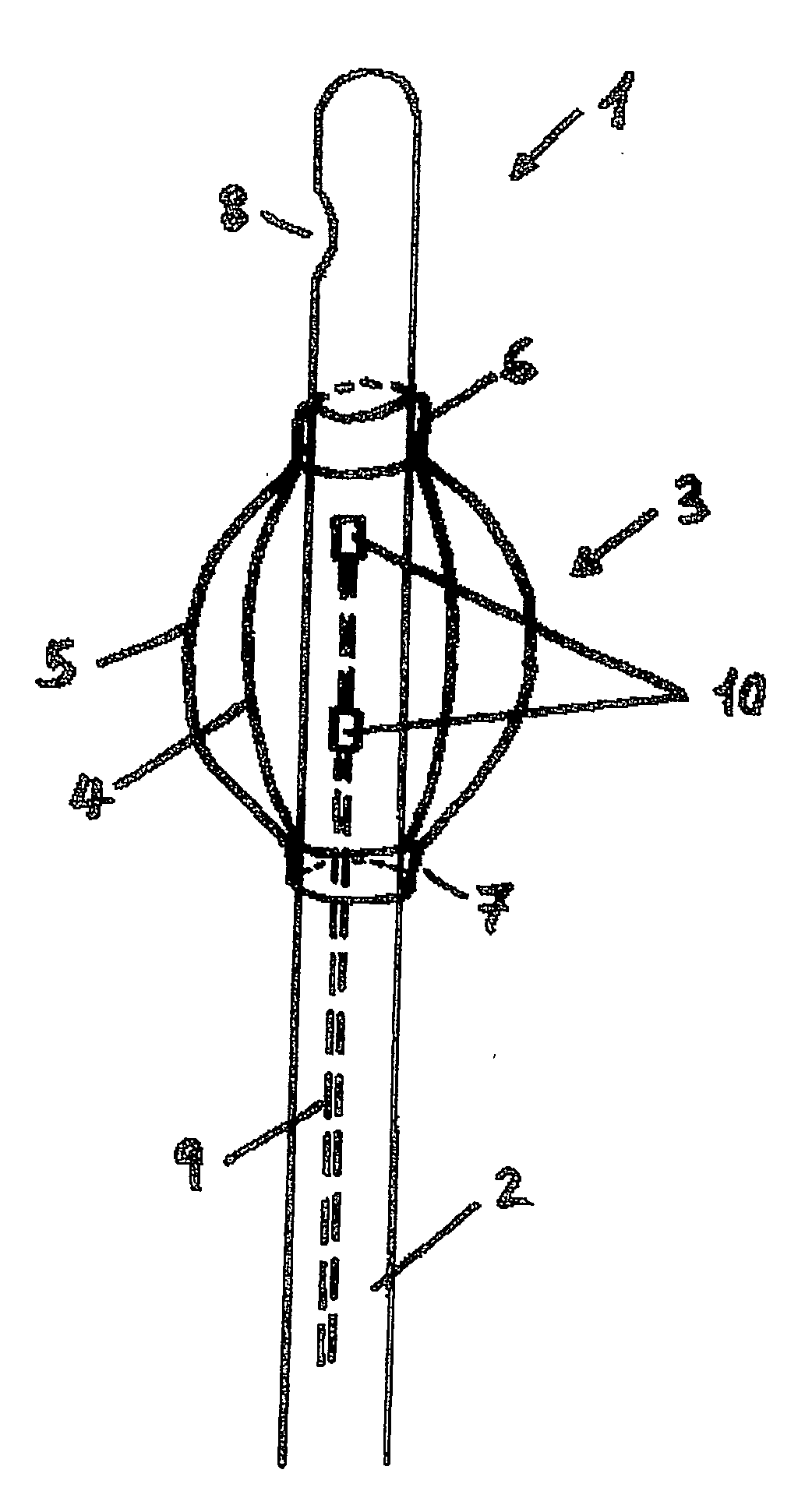
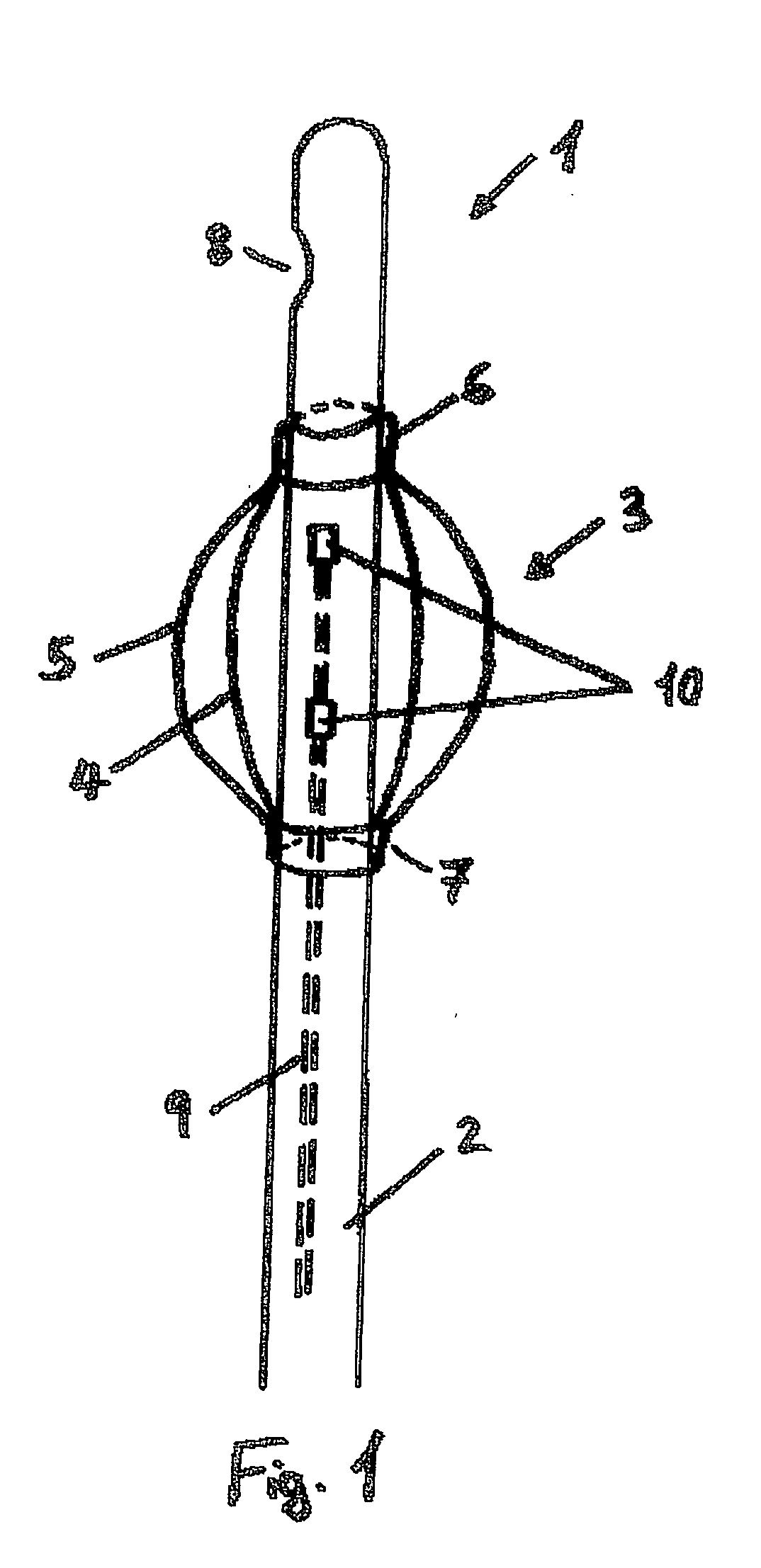
[0036]FIG. 1 shows the distal end of a bladder catheter 1 in a part-sectional, lateral view. Balloon element 3, which is shown in a sectional view both as base-state balloon 4 (volume at rest) and as inflated balloon 5 (working volume), is fastened to catheter shaft 2. Balloon element 3 is made of a polyurethane-based material; in its form as base-state balloon 4, it has a wall thickness of 5 to 20, preferably of 5-15 μm. It is provided with shaft pieces 6 and 7, via which it is bonded to catheter shaft 2. At its distal end, hollow catheter shaft 2 has opening 8, via which urine can flow out of the urinary bladder. A filling channel 9 situated in the wall of catheter shaft 2 leads to opening or plurality of openings 10 in catheter shaft 2, which is / are placed in the region of balloon element 3.

[0037] Once catheter 2 is introduced into the urinary bladder through the urethra, a suitable fluid, directed through channel 9 and opening(s) 10 into balloon element 3, fills balloon element...


PUM

PropertyMeasurementUnit
Fractionaaaaaaaaaa
Fractionaaaaaaaaaa
Thicknessaaaaaaaaaa

Abstract

A bladder catheter for transurethral introduction into the urinary bladder by the urethrae, includes an elastic catheter shank with a fillable balloon element secured thereto and connected to a filling channel incorporated into the wall of the catheter shank. The balloon element and the catheter shank are made of polyurethane, a polyurethane-polyvinylchloride mixture or similar polyurethane-based material.

Description

FIELD OF THE INVENTION [0001] The present invention is directed to a bladder catheter for transurethral introduction into the urinary bladder through the urethra, composed of a flexible catheter shaft having a refillable balloon element secured thereto, which communicates with a filling channel integrated in the wall of the catheter shaft. BACKGROUND [0002] When providing health care, the use of bladder catheters is often required. Bladder catheters in use today are composed of a flexible catheter shaft, to whose distal end, which is placed in the urinary bladder, a fluid-refillable ballon element is fastened. The catheter shaft has a filling channel, which leads into the balloon interior via an opening in the catheter wall. The main purpose of the balloon element is to securely mechanically anchor the catheter in the urinary bladder. In addition, when placed in the opening of the bladder, the balloon has a certain sealing function and prevents urine from flowing out of the bladder,...

Claims


Application Information

Patent Timeline
IPC IPC(8): A61F2/958A61L29/04A61L29/06A61M25/00
CPCA61L29/049A61L29/06A61M25/0017A61M25/10A61M25/1029A61M25/1036A61M2210/1085A61M25/1038C08L75/04
Inventor GOEBEL, FRED
Owner AVENT INC
Why Eureka
Try Eureka