Percutaneous puncture sealing system

a puncture sealing and percutaneous technology, applied in the field of percutaneous puncture sealing system, can solve problems such as the inability to ensure the punctur

Inactive Publication Date: 2005-03-24
CATES CHRISTOPHER U +2
View PDF37 Cites 89 Cited by
  • Summary
  • Abstract
  • Description
  • Claims
  • Application Information

AI Technical Summary

Benefits of technology

[0006] The method of the invention is one exemplary embodiment comprises depositing a biocompatible sealing material such as a biocompatible adhesive along at least that portion of the puncture adjacent the body cavity in a patient while preventing passage of the adhesive out of the end of the puncture into the body cavity, and allowing the adhesive to bond the body tissue around the puncture to close the puncture without passage of the adhesive into the body cavity. The sealing material may be prevented from passing out of the end of the puncture into the body cavity by temporarily closing that end of the puncture through the body of the patient opening into the body, cavity while the sealing material is deposited into the puncture. The temporary closing mechanism may be removed through the sealing material after the seal is established. The sealing material may be a single or multiple component fibrin adhesive. To maintain the adhesive in a prepared but uncured condition, it may be maintained in a frozen state or it may be mixed as an incident to the depositing of the adhesive into the puncture. Likewise, where the fibrin is activated by exposure to some condition such as irradiation with ultraviolet light, exposure to heat, or the like, it may be so exposed to such condition just prior to or during installation in the puncture. To insure access through the sealing material to the end of the puncture at the body cavity for the temporary closing mechanism, a central tube may be preinstalled through the sealing material through which the temporary sealing mechanism passes as the sealing material is installed in the puncture. The central tube also allows the collapsed expandable portion of the temporary sealing mechanism to be withdrawn there through after the sealing material is installed. A bioabsorbable separator member may also be installed between the leading end of the sealing material and the temporarily closed end of the puncture to insure that none of the sealing material inadvertently passes out of the end of the puncture and into the body cavity. The separator member may also promote sealing of the puncture in addition to the sealing material. The method of the invention is also directed to preparing a fibrin adhesive for use in bonding body tissue comprising the steps of forming the fibrin adhesive into a prescribed shape, and then freezing the fibrin adhesive while in the prescribed shape to maintain the shape. The method may also include mounting the frozen fibrin adhesive on a central tube extending therethrough. Where the central tube is flexible, it may be internally supported while the frozen fibrin is installed thereon.

Problems solved by technology

One of the primary problems associated with the prior art is the inability to insure that the puncture or incision is sealed along its length while at the same time insuring that part of the sealing material does not protrude from the puncture into the body cavity after the puncture has been sealed.
This is particularly critical when sealing punctures into blood vessels because any dislodgement of the sealing material from the puncture can cause an embolus while any protruding sealing material from the puncture into the blood vessel can serve to undesirably restrict the blood flow past the site (i.e., thrombosis).

Method used


Image

  • Percutaneous puncture sealing system
  • Percutaneous puncture sealing system
  • Percutaneous puncture sealing system

Examples


first exemplary embodiment

of Installation Arrangement

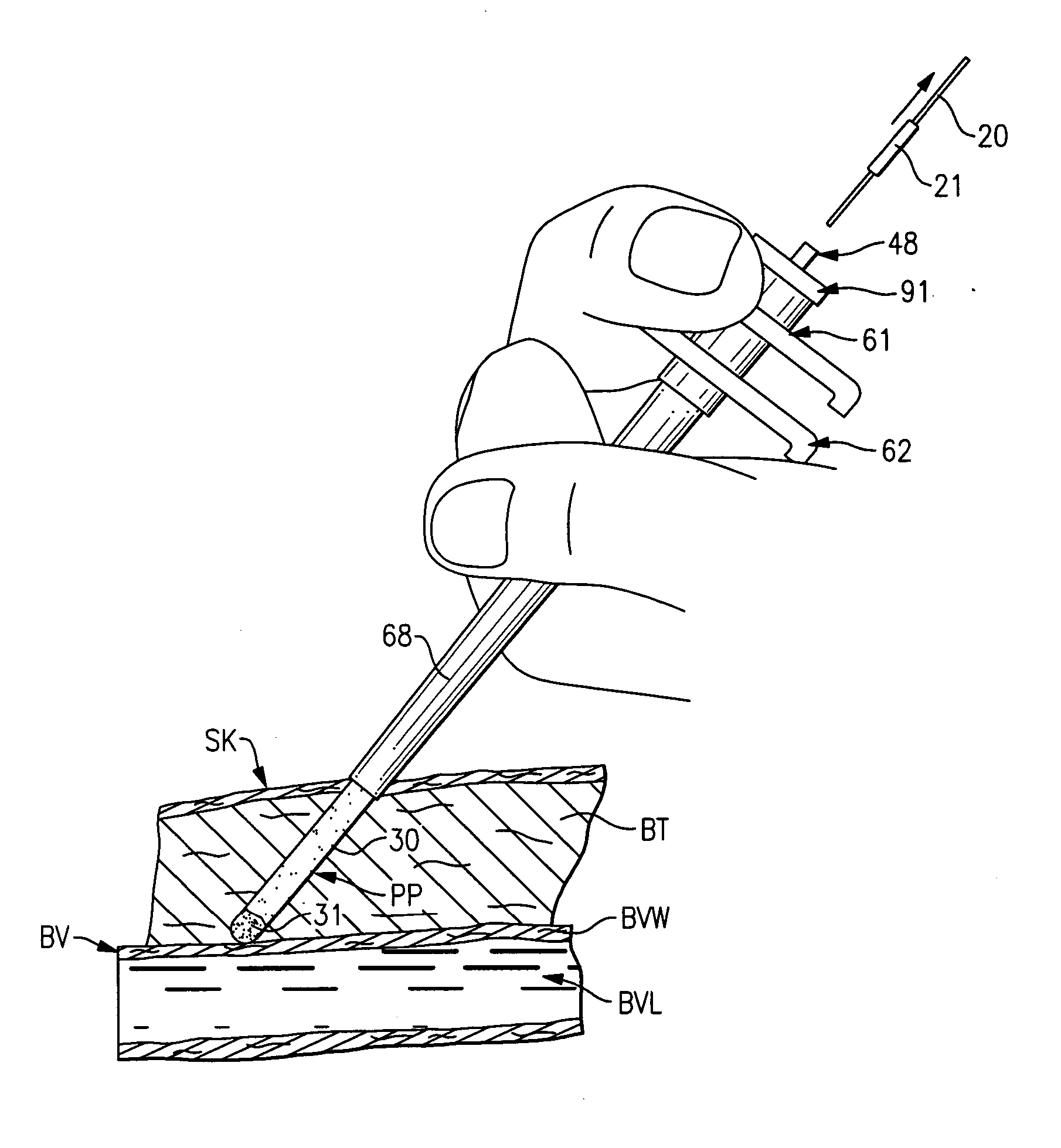
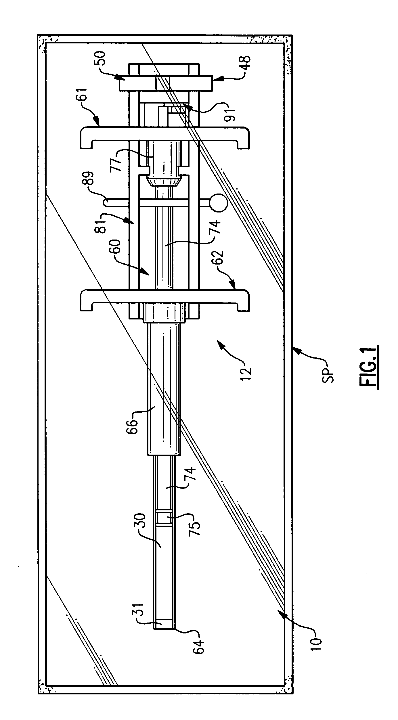
[0069] The first exemplary embodiment of the installation arrangement 12 is best seen in FIGS. 7-9. The installation arrangement 12 includes a delivery assembly 60 to carry the sealing material member 30 and separator member 31 and a plunger means 61 to hold the members 30 and 31 in a fixed position while the delivery assembly 60 is moved relative thereto.

[0070] The delivery assembly 60 seen in FIG. 7 includes a delivery tube 62 with a projecting leading end 64 thereon and with a pair of opposed gripping ears 65 at the opposite end thereof. The delivery tube 62 has an elongate tubular side wall 66 with central axis A4. The side wall is stepped intermediate its length so as to form a thinner puncture entering section 68 adjacent the leading end 64 and a thicker base section 69 at the trailing end of the side wall 66. The puncture entering section 68 has a length L4 greater than the greatest length of puncture PP likely to be encountered so that the base se...

second exemplary embodiment

of Installation Arrangement

[0097] The second exemplary embodiment of the installation arrangement designated 112 is best seen in FIGS. 31-40. The installation arrangement 112 is designed to place a flowable sealing material 130 into the puncture PP and uses the separator member 31 to separate the flowable sealing material 130 from the blood vessel wall and the end of the puncture opening into the blood vessel lumen BVL. The installation arrangement 112 includes a sheath assembly 140 into which a delivery assembly 160 carrying the sealing material 130 and separator member 31 is slidably mounted, and a plunger means 161 to hold the material 130 and member 31 in a fixed position while the delivery assembly 160 is moved relative thereto and while the sheath assembly 140 is moved relative to the delivery assembly 160 as will become more apparent.

[0098] The sheath assembly 140 seen in FIG. 31 includes a sheath tube 141 with a projecting leading end 142 thereon and with a pair of opposed ...

third exemplary embodiment

of Installation Arrangement

[0107] The third exemplary embodiment of the installation arrangement designated 212 is best seen in FIGS. 41-45. The installation arrangement 212 is also designed to place a flowable sealing material 230 into the puncture PP and uses the separator member 31 to separate the flowable sealing material 230 from the blood vessel wall and the end of the puncture opening into the blood vessel lumen BVL. The installation arrangement 212 includes a delivery assembly 260 carrying the sealing material 230 and separator member 31, and a plunger means 261 to hold the material 230 and member 31 in a fixed position while the delivery assembly 260 is moved relative thereto as will become more apparent.

[0108] The delivery assembly 260 seen in FIGS. 41 and 42 includes delivery tube 262 with a projecting leading end 264 thereon and with a pair of opposed gripping ears 265 at the opposite end thereof. The delivery tube 262 has an elongate tubular side wall 266 with central ...


PUM


Abstract

A method of sealing percutaneous punctures in a patient's body that open into an internal body cavity using a sealing material such as a fibrin adhesive while preventing the sealing material from entering the body cavity. An apparatus for delivering the sealing material is also disclosed.

Description

CROSS-REFERENCE TO RELATED APPLICATIONS [0001] The present application is a continuation of copending application Ser. No. 08 / 938,017, filed Sep. 12, 1997, which is a continuation of application Ser. No. 08 / 247,069, filed May 20, 1994, now abandoned, which is a continuation-in-part of Ser. No. 07 / 817,587, filed Jan. 7, 1992, now U.S. Pat. No. 6,056,768, the disclosures of which are herein incorporated. BACKGROUND OF THE INVENTION [0002] This invention relates generally to the sealing of surgically produced punctures for different medical procedures and more particularly to the sealing of such punctures using a sealing material ejected into the puncture. [0003] Certain medical procedures require the percutaneous puncturing of the body tissue of a patient to gain access to a cavity in the body to perform the medical procedure. One general example of such procedures is the puncturing the body tissues and the blood vessel wall to gain access to the interior of the vascular system of the...

Claims


Application Information

Patent Timeline
Patent Type & Authority Applications(United States)
IPC IPC(8): A61B17/00A61B17/08
CPCA61B17/00491A61B2017/0065A61B2017/00637A61B17/0057
Inventor CATES, CHRISTOPHER U.HORNAK, ROBERT C.STEPHENS, FRANK H. JR.
Owner CATES CHRISTOPHER U
Why Eureka
Try Eureka