Digital programmable delay scheme with automatic calibration

a digital programmable delay and automatic calibration technology, applied in pulse generators, pulse manipulation, pulse techniques, etc., can solve the problems of changing the value of the delay, the state of the timing delay technology, and the difficulty of accurately maintaining the clock signal at a desired frequency over pvt, so as to achieve accurate and relatively easy program and set the delay, save power, and calibrate the set delay

Active Publication Date: 2005-03-31
AVAGO TECH INT SALES PTE LTD
View PDF1 Cites 25 Cited by
  • Summary
  • Abstract
  • Description
  • Claims
  • Application Information

AI Technical Summary

Benefits of technology

[0009] The present invention overcomes shortcomings of the current techniques. The present invention has the ability to accurately and relatively easily program and set the delay to the desired value with the actual circuits in which the accuracy will depend on the step size of the programmable delay cell. Using current technology, designing a delay cell with the step sizes of 20 picoseconds or smaller is quite achievable. The present invention can set the desired delay to within one step size. The present invention has the ability to calibrate the set delay for process, voltage, and temperature variations by allowing each delay network or device to adjust the delay of its programmable delay cell. The method and circuit of the present invention uses minimal power and die area. With the exception of the programmable delay cell, all other cells used to design the logic are not timing critical. After the calibration mode, the counters and the rest of the logic may be disabled to save power. Since the programmable delay cell and clock buffers are also used in the actual circuit, there is almost no additional power consumption.

Problems solved by technology

The current state of timing delay technology is faced with four major issues.
Second, as the clock rate increases in digital integrated circuits, it becomes more challenging to accurately maintain the clock signal at a desired frequency over PVT (process, voltage, and temperature) variations.
Unfortunately, these variations also change the value of the delay.
As the complexity of circuit designs grow, so does the need to support various timing and speed requirements.
Unfortunately, none of the current solutions have been able to solve all of the above problems.
Although PLLs and DLLs are proven techniques to retime the clock or delay the clock 90, 180, or 270 degrees and to calibrate and adjust the delay and / or frequency over PVT, they consume a relatively large amount of power, usually require large die area, are very sensitive to switching noise, and are usually limited to shifts of 90, 180, 270 and 360 degrees only.
Fixed delay cells, an alternative to PLLs and DLLs, are small and easy to use, but they are not PVT calibrated and they are limited to one frequency only.
These and other currently available digital delay schemes are performed for some specific applications, but they lack the flexibility and require too much die area for the current and forthcoming technology.

Method used


Image

  • Digital programmable delay scheme with automatic calibration
  • Digital programmable delay scheme with automatic calibration
  • Digital programmable delay scheme with automatic calibration

Examples


Embodiment Construction

[0019] Reference will now be made in detail to the presently preferred embodiments of the invention, examples of which are illustrated in the accompanying drawings.

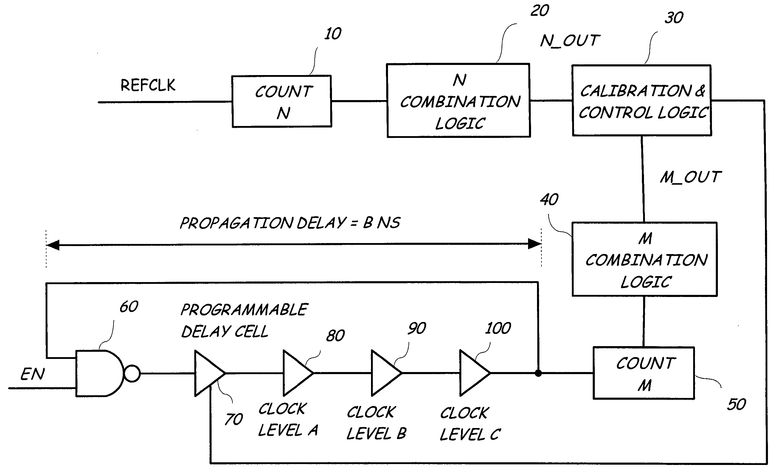
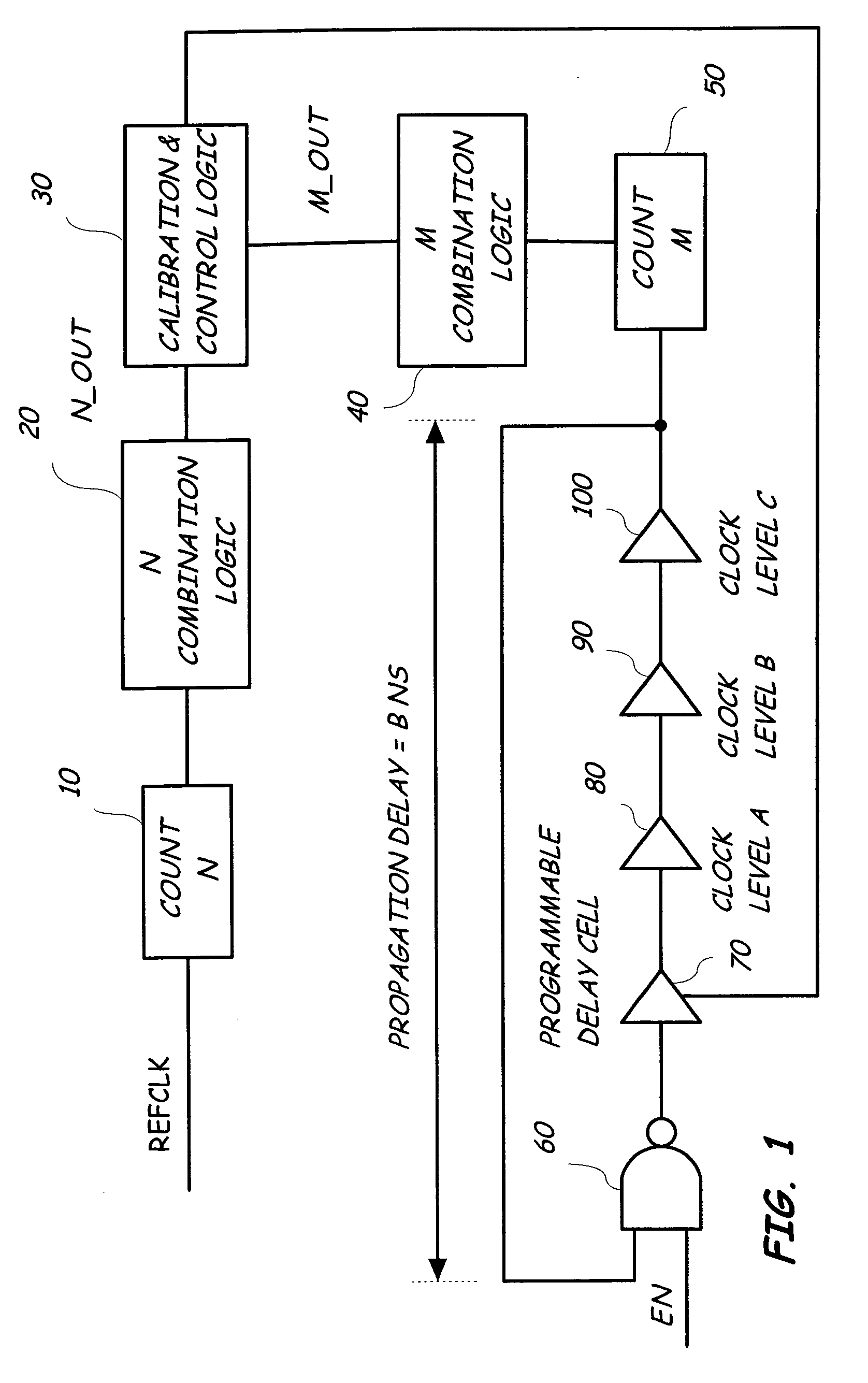
[0020] The present invention relates to a method and circuit for setting a programmable delay cell in a signal path and using a reference clock to calibrate the oscillator clock frequency of an oscillator that includes the delay cell. The circuit preferably uses two counting circuits or counters that are controlled by calibration and control logic in which one counter is clocked by the reference clock and the other is clocked by the oscillator circuit clock. In general, after a predetermined time, the calibration and control logic compares the two count values and determines if the programmable delay cell of the oscillator circuit needs to be adjusted. In a preferred embodiment, the sequence followed in the method is to clear the counters, start the counters, stop the counters, compare the counts, and, then, accordingly ...


PUM


Abstract

The digital programmable delay scheme with automatic calibration is an alternative to PLLs, DLLs, fixed delay cells and other methods of delay. The method and circuit sets a delay in a programmable delay cell in an oscillator circuit and uses a reference clock to calibrate the oscillator clock frequency. The programmable delay, once set, may then be used to determine a desired delay for a signal that passes through the programmable delay cell as well as another portion of the oscillator circuit. The circuit preferably uses two counters that are controlled by calibration and control logic in which one counter is clocked by the reference clock and the other is clocked by the oscillator circuit clock. After a predetermined time, the calibration and control logic compares the two count values and determines if the programmable delay cell of the oscillator circuit needs to be adjusted. If the oscillator circuit is determined to need adjustment, the calibration and control logic circuit so adjusts the programmable delay cell. The resulting circuit is small, flexible, and PVT calibrated and consumes very little power. It can be used with any reference clock to support various timing requirements at different frequencies.

Description

FIELD OF THE INVENTION [0001] The present invention generally relates to the field of timing in integrated circuits, and particularly to controlling a delay along a signal path for a high speed integrated circuit signal. BACKGROUND OF THE INVENTION [0002] Delay circuits are used to shift signals and / or set oscillator frequencies. A common oscillator circuit is created through a series of stages in which the output of one stage is input to the next state and the output of the last stage of the oscillator is fed back to the first stage of the oscillator. Each stage of an oscillator represents a propagation delay. For example, three inverters connected in series in which the output of the last inverter is input to the first inverter creates an oscillator in which an oscillator clock frequency has a period equal to twice the sum of the propagation delays of each inverter. [0003] The current state of timing delay technology is faced with four major issues. First, it is desirable to accur...

Claims


Application Information

Patent Timeline
Patent Type & Authority Applications(United States)
IPC IPC(8): H03K3/03H03K5/00H03K5/13H03K5/135H03K5/15H03L7/081H03L7/099
CPCH03K3/0315H03K5/135H03K5/15013H03K5/133H03K2005/00156H03L7/0812H03L7/0995H03K2005/00071H03L7/0814
Inventor HUI, KEVENHAO, HONG
Owner AVAGO TECH INT SALES PTE LTD
Why Eureka
Try Eureka