Low permittivity lubricant for magnetic disk drive systems

a magnetic disk drive and permittivity technology, applied in the field of low permittivity lubricant for magnetic disk drive systems, can solve the problems of increasing static charge in the system, affecting the operation of the disk drive, so as to achieve the effect of reducing the relative electrical permittivity and reducing the electrostatic discharg

Inactive Publication Date: 2005-03-31
WESTERN DIGITAL TECH INC
View PDF14 Cites 24 Cited by
  • Summary
  • Abstract
  • Description
  • Claims
  • Application Information

AI Technical Summary

Benefits of technology

In another embodiment, the invention provides a disk drive system similar to the above disk drive system except that the system is prone to experience electrostatic discharge between a magnetic disk and a slider in operative association with the magnetic disk. Like the above system, the disk is coupled to a rotor, which, in turn, is coupled to a motor. A stator for rotatably retaining the rotor is also provided. By replacing the lubricant in the bearing with one that has lower relative electrical permittivity, electrostatic discharge is reduced. For example, peak electrostatic discharge between the magnetic disk and the slider may be reduced from at least about 200 nA to no more than about 50 nA.

Problems solved by technology

A problem common to many disk drive systems relates to the tendency of the system to accumulate static charge.
Such charge may build up, uncontrollably discharge, and damage various components of the disk drive.
For example, a voltage difference between the heads and disks can provide a potential energy discharge that can harm the heads and the disk media itself.
Although the initial voltage differences between components of a disk drive system can be kept to near zero, static charging typically accumulates in a disk drive system during operation, thereby building up voltage differences between components of the disk drive system.
When surfaces rub against each other in a bearing, electron and ion exchange or charge separation may occur, thereby resulting in tribocharging.
Due to the close proximity of surfaces in a disk drive platter, even a small charge imbalance forms potential differences on the order of volts.
Dielectric lubricants generally lack the capability to allow for dissipation of accumulated charge.
In particular, it has been discovered that disk drives that employ highly conductive lubricants may nevertheless experience a surprisingly high peak discharge current because the lubricants themselves may accumulate excessive static charge.

Method used


Image

  • Low permittivity lubricant for magnetic disk drive systems
  • Low permittivity lubricant for magnetic disk drive systems
  • Low permittivity lubricant for magnetic disk drive systems

Examples


example

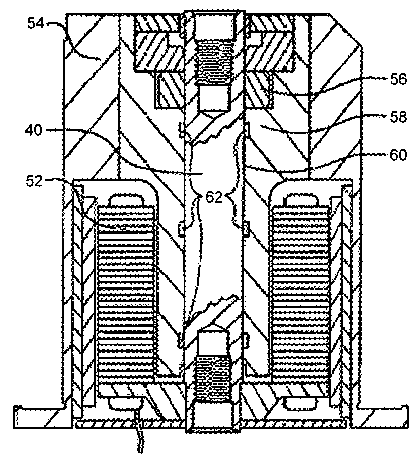
To determine the performance capabilities of various lubricants in such improved disk drives, various lubricant formulations were prepared for experimental evaluation. In particular, the dielectric properties of the lubricants were characterized. Motors were built with these formulations, and the motor running voltage and peak discharge current were measured. A series RC equivalent circuit model was developed to relate the dielectric properties of the lubricants to the peak discharge current and the electric energy associated with the charge accumulated in the bearing.

All lubricant formulations were made from a lubricating medium comprised of a base oil with one or more additives. The base oil used was neopentyl glycol dicaprate (NPG). NPG is also known as 2,2-dimethyl-1,3-propanediyl didecanoate (CAS 27841-06-1). Depending on lot, trace amounts of butylated hydroxy toluene (BHT) stabilizer were detected by nuclear magnetic resonance (NMR) spectroscopy. Formulation Oil S was prep...


PUM

PropertyMeasurementUnit
thicknessaaaaaaaaaa
wt %aaaaaaaaaa
thickaaaaaaaaaa

Abstract

An improved disk drive system that employs a lubricant with improved charge control is provided. The disk drive system is comprised of a rotatably mounted magnetic disk. A rotor is coupled to the disk and rotatably retained by a stator. A bearing is formed that serves as an interface between the stator and the rotor. A motor coupled to the rotor rotates the magnetic disk via the rotor. Located in the bearing is a lubricant having a low relative electrical permittivity.

Description

TECHNICAL FIELD The invention relates generally to disk drive systems that employ a lubricant having a low relative electrical permittivity. The invention also relates to the use of a charge-control additive to reduce the electrical charge of a lubricant. BACKGROUND Computer disk drives, e.g., hard disk drives, use a motor to turn at least one magnetic disk at high speeds. Typically, the magnetic disk is coupled to a rotor, which, in turn, is coupled to the motor for rotating the magnetic disk via the rotor. A stator is also provided to retain the rotor. A bearing serves as an interface between the stator and the rotor. During operation, lubricant is typically required and may be provided in the bearing. For example, the bearing may include a pair of magnetic fluid seals, several capillary holes or channels, and a lubricant flowing within the capillary channels that is held in place by a barrier film. Disk drive systems also include at least one read / write transducer or “head” th...

Claims


Application Information

Patent Timeline
Patent Type & Authority Applications(United States)
IPC IPC(8): F16C33/10C10M133/12C10M149/22C10N20/00C10N30/00C10N40/16F16C17/10G11B17/028G11B19/20
CPCC10M169/04C10M2207/026C10M2207/2835C10M2215/064C10M2215/065F16C2370/12F16C17/107F16C33/109G11B17/028G11B17/0287C10N2240/204C10N2040/18
Inventor BURNS, JOHN M.FU, TA-CHANGHANLON, ANDREW K.HIGNITE, CHARLESKARIS, THOMAS E.KROEKER, RICHARD M.WONG, STANLEY Y.
Owner WESTERN DIGITAL TECH INC
Why Eureka
Try Eureka