Nuclear plant spent fuel low temperature reactor

a nuclear reactor and nuclear plant technology, applied in nuclear reactors, thermal reactors, nuclear energy generation, etc., can solve the problems of high backup reactivity and not only criticality of cores, and achieve the effect of low construction cost and good safety and reliability

Inactive Publication Date: 2005-03-31
NUCLEAR POWER INSTITUTE OF CHINA
View PDF6 Cites 5 Cited by
  • Summary
  • Abstract
  • Description
  • Claims
  • Application Information

AI Technical Summary

Benefits of technology

[0010] This invention is aimed at supplying a low-temperature and low-pressure reactor, which directly uses NPP spent fuel for desalination, heat supply and isotope production, and is featured with low construction cost and good safety and reliability.
[0015] 3. Appropriate moderate reflector is added around the core as necessary to reduce neutron leakage and increase backup reactivity;
[0022] 1. The neutron chain reaction device that reuses the spent fuel from the nuclear power plant as nuclear fuel promotes the utilization value of uranium resource without any new spent fuel production. The fuel assemblies discharged from the nuclear power plant can be loaded into the reactor followed by proper inspection. Therefore, the costs of fuel as well as investment and operation are significantly reduced, economic and environmental effects are remarkable.
[0023] 2. Because of low power density and passive residual heat removal, the core will not be melt down in case of accidents. With at least one airtight shield and “no radiological consequence”, this reactor is of high inherent safety and good safety performance.
[0025] 4. Technically special underwater fuel handling canal is used to replace conventional fuel handling system. The simplified handling process and equipment facilitate operation and enhance safety.

Problems solved by technology

The core can not only reach criticality, but also has much backup reactivity to meet operation requirements.

Method used


Image

  • Nuclear plant spent fuel low temperature reactor
  • Nuclear plant spent fuel low temperature reactor
  • Nuclear plant spent fuel low temperature reactor

Examples


example 2

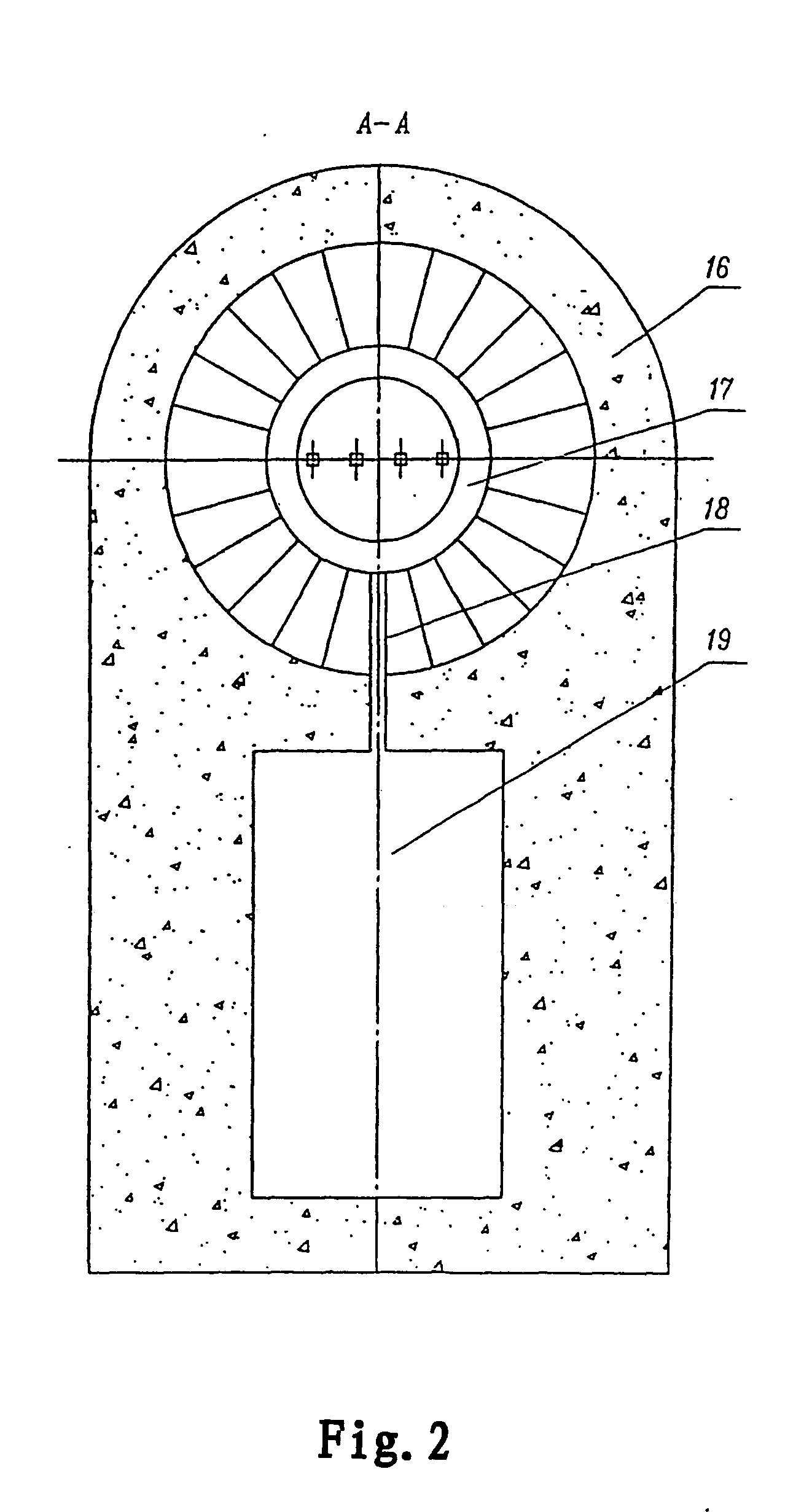
[0031] Unlike example 1, another configuration is core pool filled with full of air, the atmosphere is used to form pressure at outlet, as shown in FIG. 2. A sealing cover (11) like a cap is located on the top of the core pool (8) to form pressurized air cavity (17), which is filled with pressurized air or nitrogen or helium. On the lower part is the water level fluctuation area to form an airtight shield. Meanwhile, on the top of the core pool there is an airtight shield to form secondary air shield. The area between the sealing cover on the top of the core pool and the airtight shield extracts negative pressure to prevent radioactive gases from releasing.

[0032] In order to remove the hydrogen and oxygen from water decomposition within the sealing cover and the gaseous iodine and radioactive noble gases from fuel fission, the invention designs an air circulation circuit (not shown in the figure) to recombine hydrogen and oxygen as well as removing iodine and noble gases out.

[0033...


PUM


Abstract

A low-temperature NPP spent fuel reactor is disclosed, wherein the core is located in the core vessel and is fuelled by NPP spent fuel; a sealing cover and / or an air-tight shield are located on the top of the pool, forming at least one air shield. A pressurizer is set on the coolant inlet nozzle that improves the static pressure and maintains the pressure at the core outlet. On the side of the pool is an underwater handling canal, which is connected with the spent fuel storage pond. This invention uses NPP spent fuel as its nuclear fuel, promoting the utilization value of uranium resource, with good safety, economical and environmental effects. The radioactive gases discharged to environment during normal operation and under accident conditions can meet the requirements of “no radiological consequence”. Its simplified handling process and equipment facilitate operation and improve safety. The reactor can be used for desalination, low-temperature heat supply and isotope production.

Description

FIELD OF TECHNOLOGY [0001] This invention relates to a nuclear reactor technology, specifically to a low-temperature nuclear reactor using NPP spent fuel as its nuclear fuel. TECHNICAL BACKGROUND NPP spent fuel is the fuel, which reaches expected bum-up but is below its limit and can't meet the requirements of NPP operation and hence is discharged. [0002] Generally, about 0.9-1.1% U-235 remains in the spent fuel assembly discharged from nuclear power plant and some fissile materials such as 0.6% Pu-239 and 15% Pu-241 are generated. They are usable resources. [0003] At present, two kinds of basic policies are adopted for NPP spent fuel management in the world. One is “once-through” fuel cycle, whereby NPP spent fuel is directly disposed after interim storage without reprocessing. The second is spent fuel reprocessing, whereby the remaining U-235 and the generated Pu-239 in spent fuel are extracted through reprocessing and fabricated into MOX element to be reused as NPP fuel. Obviousl...

Claims


Application Information

Patent Timeline
Patent Type & Authority Applications(United States)
IPC IPC(8): G21C1/14
CPCG21C1/14Y02E30/40G21Y2004/60G21Y2002/601Y02E30/30
Inventor LI, YULUNMA, FUBANGWU, YINGHUA
Owner NUCLEAR POWER INSTITUTE OF CHINA
Why Eureka
Try Eureka