
Active Ankle Foot Orthosis

a technology of active ankle and foot, applied in the field of active ankle foot orthosis, can solve the problems of increasing the risk of tripping, severe inhibition of locomotor function, and disadvantages, and achieves the effects of less kinematic differences, increased independence, and improved independen

Active Publication Date: 2005-03-31
MASSACHUSETTS INST OF TECH
View PDF37 Cites 191 Cited by
  • Summary
  • Abstract
  • Description
  • Claims
  • Application Information

AI Technical Summary

Benefits of technology

[0003] Increasingly, robotic technology is employed in the treatment of individuals suffering from physical disability, either for the advancement of therapy tools or permanent assistive devices. Initial research has focused primarily on devices that provide therapy to the arms of stroke patients. However, lower extremity robotic devices have recently been developed. When used for permanent assistance, adaptive orthoses enables disabled persons to walk with greater ease and less kinematic difference when compared to normals. Active leg prostheses also show promise. Preliminary studies report that the Otto Bock C-Leg, a microprocessor-controlled artificial knee, provides amputees with an increased independence compared with passive knee prostheses.
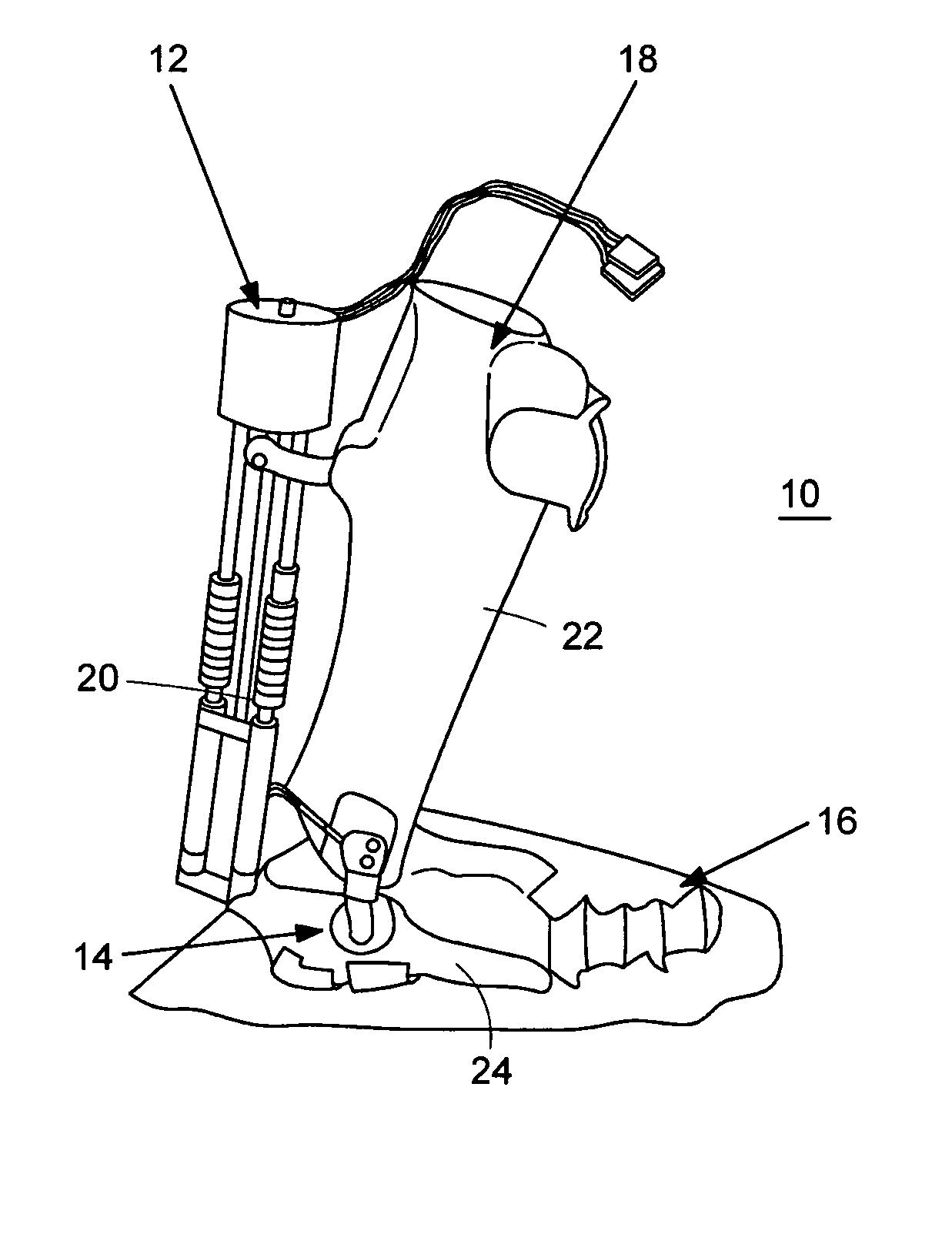
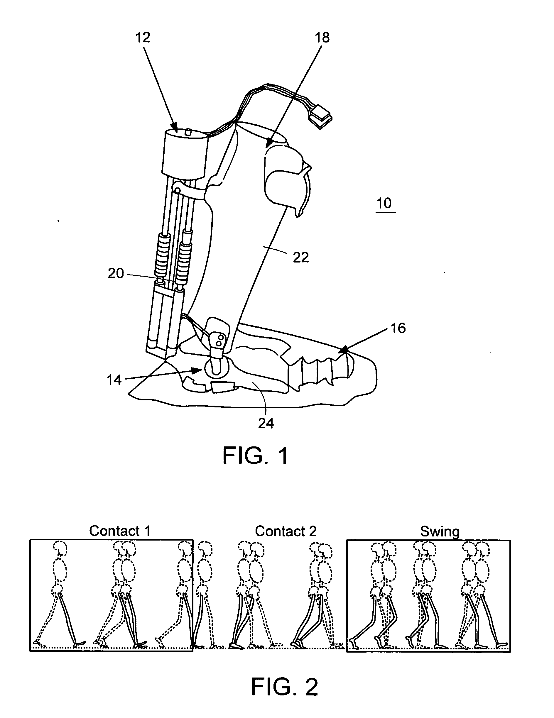
[0006] Neither AFOs nor conventional FES systems adapt to the gait of the user, adapt to step-to-step changes in gait pattern due to speed or terrain, or adapt to long-term gait changes due to changes in muscle function. In one embodiment, a computer-controlled Active Ankle Foot Orthosis (AAFO) is provided where joint impedance is varied in response to walking phase and step-to-step gait variations. The AAFO includes an actuator, such as a force-controllable Series Elastic Actuator (SEA) capable of controlling orthotic joint stiffness and damping for plantar and dorsiflexion ankle rotations.
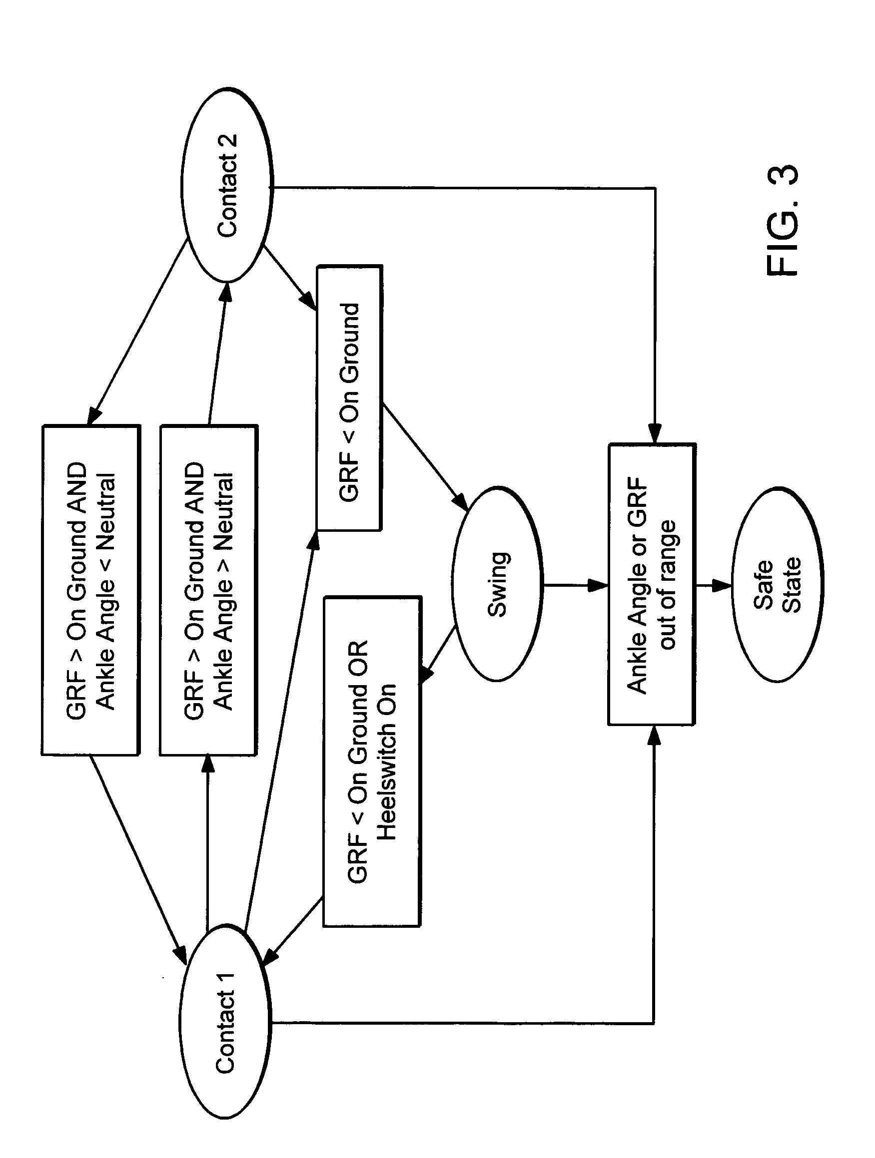
[0007] A variable-impedance orthosis has certain clinical benefits for the treatment of drop foot gait compared to both unassisted gait and conventional AFO's that include constant impedance joint behaviors. For example, the major complications of drop foot gait, namely foot slap and toe drag, can be reduced by actively controlling orthotic joint impedance in response to walking phase and step-to-step gait variations. Recent investigations have shown that for the healthy ankle-foot complex, ankle function during controlled plantar flexion closely resembles a linear torsional spring where ankle moment is proportional to ankle position. Thus, by adjusting the stiffness of a virtual linear torsional spring acting about the orthotic joint, forefoot collisions can be minimized and the slap foot complication alleviated, not only at a single speed but at every forward walking speed. Furthermore, during swing, a spring-damper (PD) control can be applied to the orthotic joint, with gains that vary with gait speed, to dorsiflex the ankle through a greater angular range to provide sufficient clearance at variable walking speeds. For individuals suffering from unilateral drop foot gait, changing orthotic joint impedance results in a more symmetric gait between affected and unaffected legs.

Problems solved by technology

Individuals may suffer from a variety of ankle foot gait pathologies, such as muscle weakness in the anterior and / or posterior compartments of the leg, which severely inhibit locomotory function.
The two major complications of drop foot are slapping of the foot after heel strike (foot slap) and dragging of the toe during swing (toe drag).
During mid-swing, toe drag prevents proper limb advancement and increases the risk of tripping.
Although AFO's offer some biomechanical benefits, disadvantages still remain.
For example, AFO's do not improve gait velocity or stride length in children with cerebral palsy.
Further, although a constant stiffness AFO is able to provide safe toe clearance in drop foot patients, the device does not reduce the occurrence of slap foot at all walking speeds.

Method used


Image

  • Active Ankle Foot Orthosis
  • Active Ankle Foot Orthosis
  • Active Ankle Foot Orthosis

Examples


example

[0039] A clinical evaluation of the AAFO 10 was conducted in the Gait Laboratory at Spaulding Rehabilitation Hospital, Boston, Mass. Drop foot participants having only a unilateral drop foot condition were selected, and on their affected side, participants did not suffer from a gait disability other than drop foot. Both participants had an absence of strongly manifesting spasms and contractures in lower extremity joints. Finally, each participant had used an AFO for at least two years and therefore was experienced at AFO ambulation. Subjects reached a stable neurological state after the incident that caused their disability. Thus, no recovery of function was expected or found. Three normal subjects were matched for gender, height, weight, and age to the drop foot participants. Subject sex, age, mass, height, and self-selected gait speed are listed in Table III.

TABLE IIIAgeMassHeightSelf-SelectedSubjectSex(yr)(kg)(m)Gait Speed (m / s)Drop FootM6279.11.791.22Drop FootM6295.41.771.07No...


PUM


Abstract

An Active Ankle Foot Orthosis (AAFO) is provided where the impedance of an orthotic joint is modulated throughout the walking cycle to treat ankle foot gait pathology, such as drop foot gait. During controlled plantar flexion, a biomimetic torsional spring control is applied where orthotic joint stiffness is actively adjusted to minimize forefoot collisions with the ground. Throughout late stance, joint impedance is minimized so as not to impede powered plantar flexion movements, and during the swing phase, a torsional spring-damper (PD) control lifts the foot to provide toe clearance. To assess the clinical effects of variable-impedance control, kinetic and kinematic gait data were collected on two drop foot participants wearing the AAFO. It has been found that actively adjusting joint impedance reduces the occurrence of slap foot, allows greater powered plantar flexion, and provides for less kinematic difference during swing when compared to normals.

Description

BACKGROUND OF THE INVENTION [0001] Individuals may suffer from a variety of ankle foot gait pathologies, such as muscle weakness in the anterior and / or posterior compartments of the leg, which severely inhibit locomotory function. For example, drop foot gait is the inability of an individual to lift or dorsiflex their foot because of reduced or no muscular activity, typically in the anterior compartment of the leg around their ankle. The major causes of drop foot include stroke, cerebral palsy, multiple sclerosis, and neurological trauma from accident or surgical complication. The two major complications of drop foot are slapping of the foot after heel strike (foot slap) and dragging of the toe during swing (toe drag). At heel strike, the foot generally falls uncontrolled to the ground, producing a distinctive slapping noise (foot slap). During mid-swing, toe drag prevents proper limb advancement and increases the risk of tripping. [0002] A conventional approach to the treatment of ...

Claims


Application Information

Patent Timeline
IPC IPC(8): A61B5/103A61F5/01
CPCA61B5/1038A61B5/1071A61B5/4519A61F2002/701A61B5/4528A61F5/0113A61F5/0127A61B5/4523A61F2/70A61F2005/0155A61H3/00A61H2003/007A61H2201/12A61H2205/10
Inventor HERR, HUGHBLAYA, JOAQUINPRATT, GILL A.
Owner MASSACHUSETTS INST OF TECH
Learn More