Bone fixation assembly and method

a technology for fixing devices and bones, applied in the field of bone fixation devices, can solve the problems of adding to the complexity of surgical techniques, and achieve the effect of reducing the assembly of small hardware pieces

Active Publication Date: 2005-03-31
STRYKER EURO OPERATIONS HLDG LLC
View PDF42 Cites 239 Cited by
  • Summary
  • Abstract
  • Description
  • Claims
  • Application Information

AI Technical Summary

Benefits of technology

[0012] According to one or more embodiments of the present invention, bone fixation assemblies are provided to connect spinal rods without any loose parts and very few steps (preferably only two steps) to lock the fixation element to the coupling member and the spinal rod to the coupling member. The assemblies of the present invention do not require any additional locking mechanism, and they reduce the assembly of small pieces of hardware during the surgical procedure.

Problems solved by technology

Each additional component or instrument required to assemble the fixation system adds to the complexity of the surgical technique.

Method used


Image

  • Bone fixation assembly and method
  • Bone fixation assembly and method
  • Bone fixation assembly and method

Examples


Embodiment Construction

[0023] Before describing several exemplary embodiments of the invention, it is to be understood that the invention is not limited to the details of construction or process steps set forth in the following description. The invention is capable of other embodiments and of being practiced or carried out in various ways.

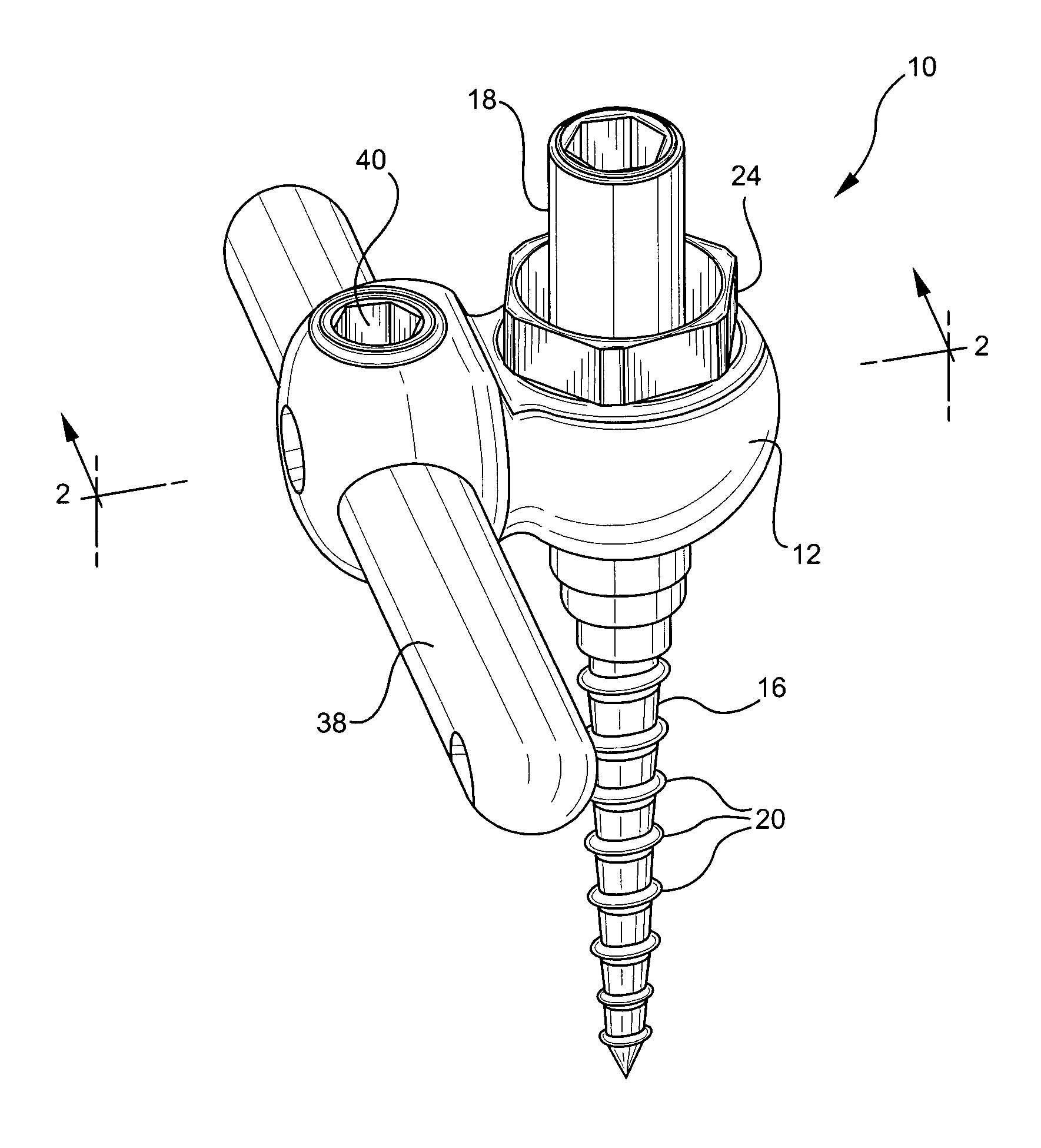
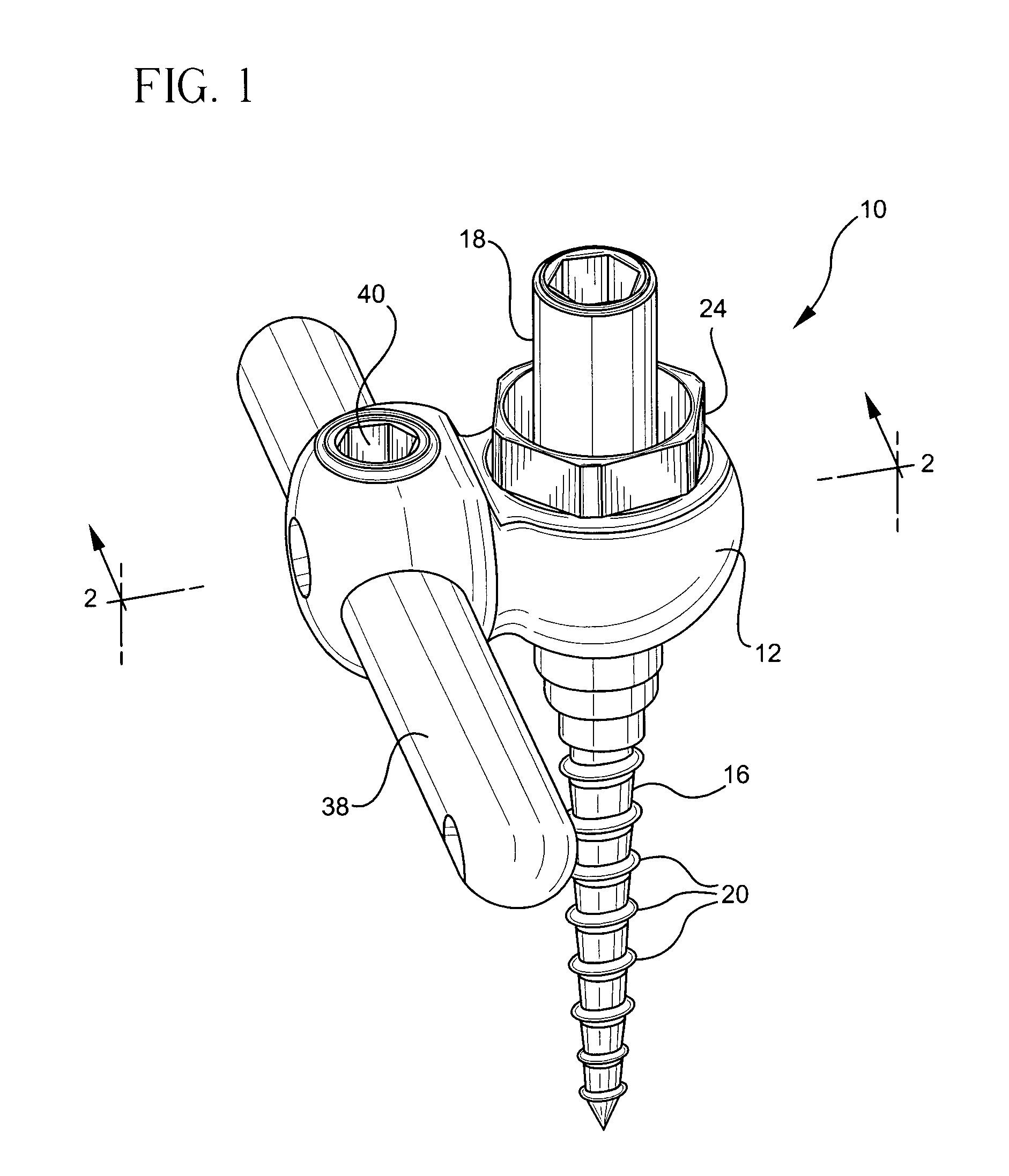
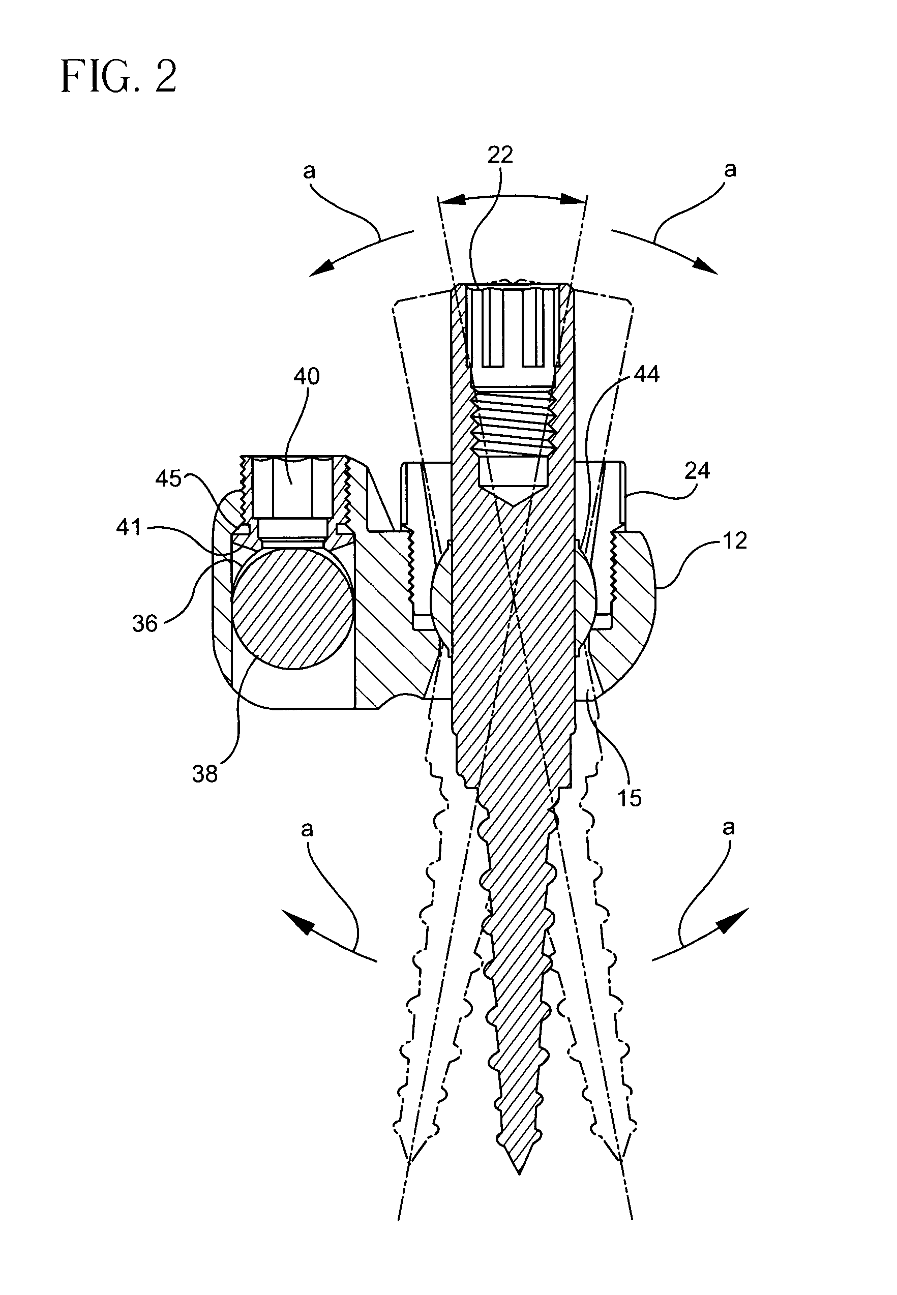
[0024] Referring now to the drawings and particularly to FIGS. 1-3, a bone fixation assembly 10, in accordance with certain preferred embodiments of the present invention, is shown. The bone fixation assembly may be secured to the pedicles 11 of vertebral bodies of a spinal column, as shown in FIG. 3. The fixation assembly includes a coupling element 12, preferably made of a biologically inert material, for example, any metal customarily used for surgical devices and particularly those used for bone screws and pins, such as titanium or stainless steel. Other suitable materials for the coupling element include, but are not limited to, alloys, composite materials, ceramic...


PUM


Abstract

A bone fixation assembly and method of fixing bones including a fixation element having a head portion, a unitary coupling element and at least one locking element. The unitary coupling element includes a first bore adapted to slidably receive the head portion of the fixation element. A first locking element is adapted to secure the head portion in the first bore.

Description

CROSS-REFERENCE TO RELATED APPLICATIONS [0001] The present application claims priority of French Application No. 0311291 filed on Sep. 26, 2003, the contents of which are hereby incorporated by reference in their entirety. FIELD OF THE INVENTION [0002] The invention relates to bone fixation devices, and in particular, to pedicle fixation assemblies and methods used in spinal fixation procedures. BACKGROUND OF THE INVENTION [0003] The spinal column is a highly complex system of bones and connective tissues that provides support for the body and protects the delicate spinal cord and nerves. The spinal column includes a series of stacked vertebral bodies, each vertebral body including an inner or central portion of relatively weak cancellous bone and an outer portion of relatively strong cortical bone. Situated between each vertebral body is an intervertebral disc that cushions and dampens compressive forces exerted upon the spinal column. A vertebral canal containing the spinal cord a...

Claims


Application Information

Patent Timeline
Patent Type & Authority Applications(United States)
IPC IPC(8): A61B17/70
CPCA61B17/7041A61B17/7035
Inventor DAVID, JEROME
Owner STRYKER EURO OPERATIONS HLDG LLC
Why Eureka
Try Eureka