Device and method for boiler superheat temperature control

a superheat temperature and boiler technology, applied in the field of steam boilers, can solve the problems of large flow, large quantity of nox, and large amount of nitrogen oxide, and achieve the effect of increasing the temperature and quality of steam, and producing more heat or energy

Inactive Publication Date: 2005-04-07
JUPITER OXYGEN CORP
View PDF21 Cites 16 Cited by
  • Summary
  • Abstract
  • Description
  • Claims
  • Application Information

AI Technical Summary

Benefits of technology

[0009] In accordance with the present invention a boiler comprising at least one primary burner using oxygen and fuel with the absence of normal combustion air for initial heating of water, a collection of water tubes, each tube having a first end in proximity to the at least one primary burner and a second end spaced apart from the first end and in proximity to a boiler steam outlet is provided. The boiler further can comprise a superheater and / or reheater in steam transfer connection with the steam outlet. At least one secondary burner is provided above the typical burner position to produce more heat or energy to increase the temperature and quality of the steam in the boiler proper and in the superheat and / or reheat regions of the boiler.
[0011] In the operation of the boiler, the primary burner, or burners, heats water flowing in the water tubes, causing the heated water to rise within the boiler. The heated water flashes to steam in the steam outlet and the steam is transferred to the superheat device. As a result of convection currents, heat is added to the steam in the superheat area, raising the temperature of the steam above the saturation point. The secondary burner provides added heat, permitting a more constant and consistent control over the heating of the steam. In this manner, appropriately heated steam is provided to a turbine, permitting the turbine to work in an efficient and proper way. In other embodiments, more than one secondary burner is provided, such that, when desired, the heat applied to the superheater elements is more carefully controllable. Because of the diminished flow of heated gases in the present embodiment, due to the use of oxygen at typically a lower flow rate than air, energy from the primary burner, or burners, is supplemented by the at least one secondary burner to overcome the insufficient heat and energy. The at least one secondary burners, placed between the level of the primary burner(s) and the steam outlet, provides heat or energy to the water in the tubes, and to the steam in the superheat zone, to provide the energy lost through the use of low flow oxygen.
[0012] In a further embodiment, the secondary burner is fed with oxygen from an oxygen generation system in place of normal combustion air in a stoichiometric proportion with the fuel, such that green house gases are minimized. As normal combustion air consisting of approximately 80% nitrogen consumes considerable heat, which is lost to exhaust, the use of oxygen from an oxygen generation system lessens the heat lost to exhaust and permits the heat of the burner to be applied to the superheater in a more efficient manner. In another embodiment, both the secondary and primary burners are fed with oxygen from an oxygen generation system in stoichiometric proportions.
[0013] The heated water flashes to steam, in the steam outlet, and the steam is transferred to the superheat device, where the secondary burner continues to provide the added heat and energy to increase the quality of steam produced. Steam from the superheater can then be fed into the turbine. In one embodiment, steam is returned from the turbine to a reheat device, where it is again placed into the presence of the heat and energy provided both by the primary and secondary burners, and is again sent to the turbine. As a result of convection currents produced by the secondary burners, heat or energy is added to the steam in areas where low flow oxygen fed burners typically have heat and energy gaps, which would otherwise allow the water in the boiler to cool. The convection currents raise the temperature of the steam above the saturation point producing desirable quantities and qualities of steam. The secondary burner provides added heat or energy, permitting a more constant and consistent heating of the steam. In this manner, appropriately heated steam is provided to a turbine, permitting the turbine to work in an efficient and proper manner.
[0014] In other embodiments of the present invention, more than one secondary burner is provided, such that, when desired, the heat or energy applied to the superheater elements can be more carefully controlled. Further, in a preferred embodiment a boiler of the present invention can be created so that it can produce greater heat or energy than needed. In such an embodiment cooling and other elements known to persons having skill in the art can be provided to bring, or attenuate, the steam to the desired heat and energy levels. It will be understood by persons having skill in the art that the use of cooling elements to produce steam having desired properties will be more effective than attempting to use heating elements, within a boiler, to heat steam to the desired levels.

Problems solved by technology

However, along with this benefit, it has been found that the burning of fuel in the presence of nitrogen rich air causes the production of nitrogen oxide (NOx), a deleterious greenhouse gas.
In prior art boilers, the burning of air in the boilers, and the necessary increased flow of air into the boiler, in order to provide a stoichiometric proportion of oxygen to complete combustion, concomitantly, causing a great amount of flow and produces great quantities of NOx.
However, because use of pure oxygen at an un-pressurized flow rate creates the stoichiometric proportion needed to consume fuel, without the need for the rapid / forced flow used with air, heat and energy are concomitantly not forced (by the pressure otherwise used to pump air into the boiler) up to the heights of the boiler.
This results in the failure of such boilers to provide an effective alternative to the prior art greenhouse gas producing furnaces.

Method used


Image

  • Device and method for boiler superheat temperature control
  • Device and method for boiler superheat temperature control

Examples


Embodiment Construction

[0020] While the present invention is susceptible of embodiment in various forms, there is shown in the drawings a number of presently preferred embodiments that are discussed in greater detail hereafter. It should be understood that the present disclosure is to be considered as an exemplification of the present invention, and is not intended to limit the invention to the specific embodiments illustrated. It should be further understood that the title of this section of this application (“Detailed Description of an Illustrative Embodiment”) relates to a requirement of the United States Patent Office, and should not be found to limit the subject matter disclosed herein.

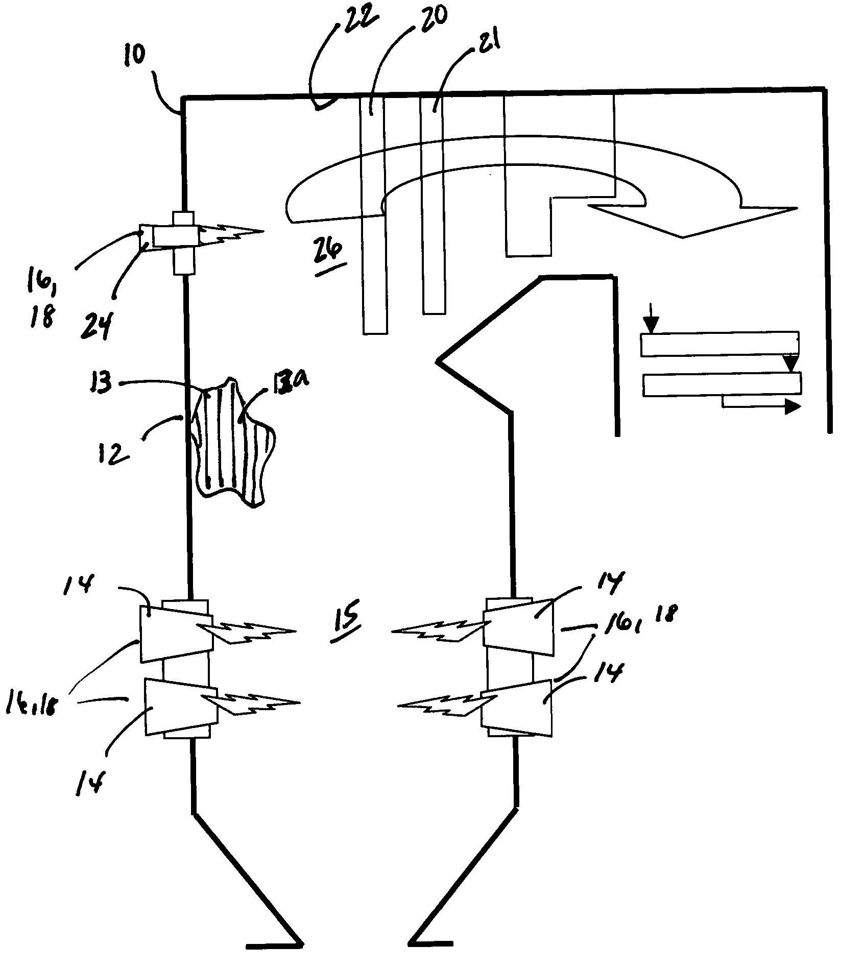
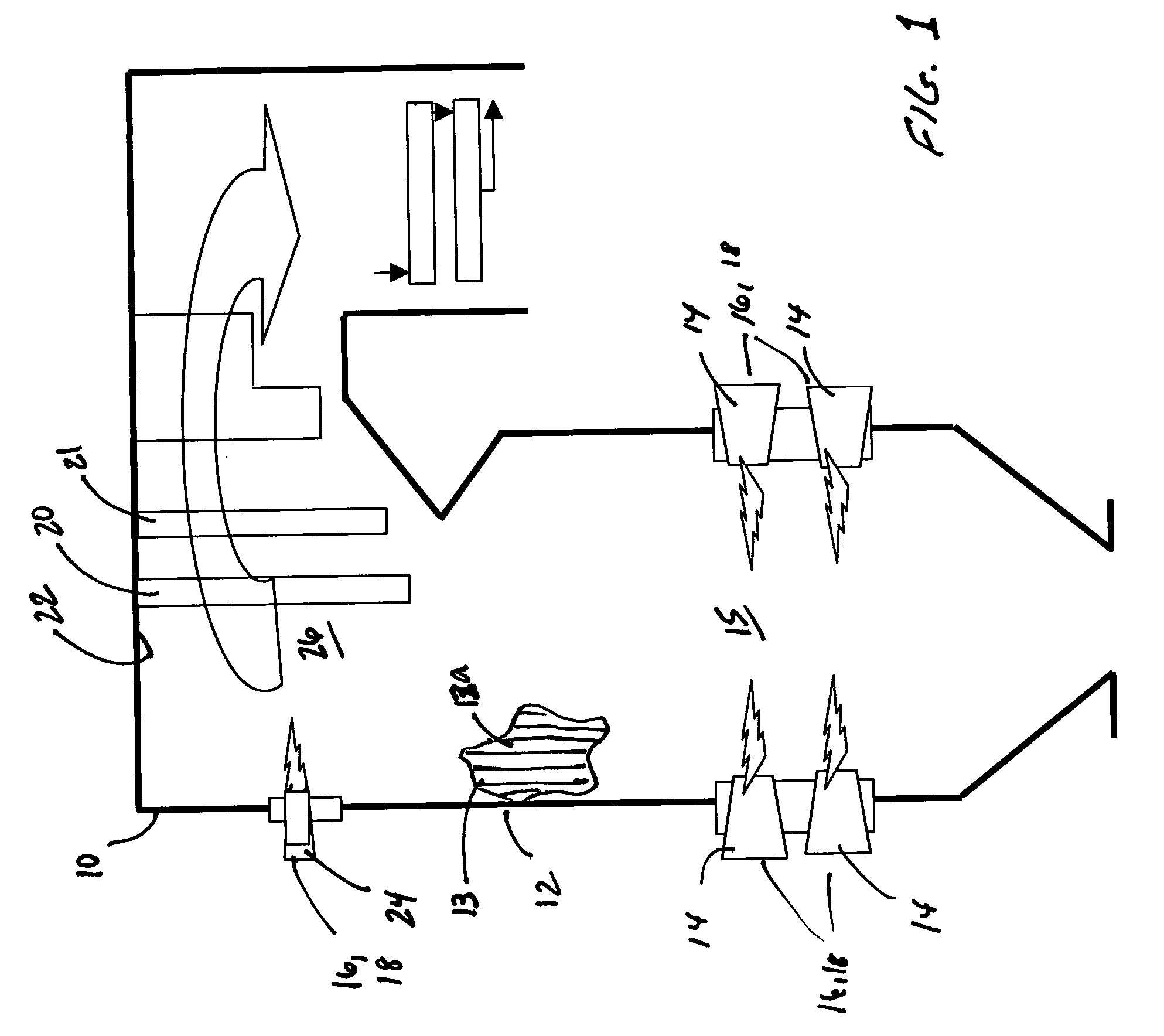
[0021] Referring to the FIGURE, a boiler 10 comprising a series of water tubes 12, which together comprise a water wall 13, is shown. The boiler 10 further comprises at least one primary burner 14, located in primary burner zone 15, connected to a source of fuel 16 and air 18. In a preferred embodiment of the present ...


PUM


Abstract

A boiler designed or retrofitted to produce less greenhouse gasses by using a substantially pure oxygen atmosphere in which to burn fuel. The boiler having a primary burner and water tubes is provided. The boiler further comprises at least one secondary burner located as needed in a zone above the primary burner area and below the boiler steam outlet. The secondary burner providing heat or energy to increase the temperature and quality of the steam. The secondary burner providing the heat or energy lost through the diminished flow rate of exhaust gases through the boiler as a result of the use of oxygen rather than pressurized air.

Description

FIELD OF THE INVENTION [0001] The present invention concerns steam boilers designed or modified to operate with oxygen and fuel with the absence of normal combustion air and requires a superheated and or reheated steam temperature control employing an advanced method of controlling the superheat and or reheat temperature of steam in the boiler above the conventional combustion region. More particularly the present invention concerns a boiler having at least one additional burner using oxygen and fuel with the absence of normal combustion air in the convection area in order to boost heat and energy at the superheat and or the reheated areas and convection regions as may be required to maintain proper steam temperatures at the outlet of the steam boiler. BACKGROUND OF THE INVENTION [0002] Power plants and or steam plants used by utility companies, industries and municipalities for, among other applications, the production of steam and electricity, typically comprise small to giant boi...

Claims


Application Information

Patent Timeline
Patent Type & Authority Applications(United States)
IPC IPC(8): F22B31/04
CPCF22B31/04Y02E20/34
Inventor GROSS, DIETRICH M.
Owner JUPITER OXYGEN CORP
Why Eureka
Try Eureka