
Maintenance service system, method and program

a service system and maintenance technology, applied in the field of maintenance service system, to achieve the effect of reducing the load of trouble-dealing work

Inactive Publication Date: 2005-04-07
NEC FIELDING
View PDF4 Cites 34 Cited by
  • Summary
  • Abstract
  • Description
  • Claims
  • Application Information

AI Technical Summary

Benefits of technology

[0033] The present invention has been implemented in view of the foregoing situation, and a first object of the present invention is to provide a system that can immediately grasp the damage imposed on the overall system in place of independent dealing, trouble sensing and reporting by a service processor in each individual system device, and thus reduce the load of a trouble dealing work to be imposed on a system manager and a maintainer in an information processing system having a server-client construction based on network connection in a multi-vendor system.
[0034] A second object of the present invention is to enable a system manager to collectively monitor the overall system and further enable a trouble report between the system manager and end users, thereby overcoming the problem of the conventional information system in which the trouble sensing and reporting method mainly focuses on the convenience of a maintenance service center and a maintenance service worker, a worker in the maintenance service center transmits and checks the trouble to the system manager and the user by telephone or the like, and a trouble dealer at the trouble-occurring place is swamped with telephone dealing from the maintenance service center and dealing with the endusers, so that an initial action to repair the trouble is delayed.
[0035] A third object of the present invention is to provide the system with trouble monitoring and reporting functions for environmental facilities and incidental facilities at the setup places of information processing devices and also trouble monitoring and reporting functions for network facilities to thereby make the function of the system complete, and also provide the system with a function of collectively managing, as the overall system, all the trouble monitoring and reporting functions which independently and individually operate in each device, by automatically transmitting necessary information to related departments and maintenance / repair companies.
[0036] A fourth object of the present invention is to provide a method in which a vendor / maker shouldering the responsibility for a server having an important function on the system management in the overall system can perform collective management on the overall system as a main body in order to avoid such a situation that the system manager must deal with each of vendors / makers individually because of the multi-vendor structure, thereby enhancing the convenience between the system manager and the users and the efficiency of the maintenance service.
[0037] A fifth object of the present invention is to provide a method in which some vendor / maker can have charge of collectively performing the system maintenance for the overall system because the operating systems in multi-vendor based large-scale systems have been designed to have the same construction, so that a system engineer of some specific vendor / maker can temporarily deal with software maintenance and collection of error messages and error logs for hardware at the initial stage when a system trouble occurs, thereby enhancing the efficiency of the maintenance service.

Problems solved by technology

However, the above-described prior art has the following problems.
However, under the recent condition that a system is constructed in a multi-vendor style using network connection which is based on a server-client construction, it has been already neither an effective function nor an effective method for coping with troubles as the whole system to handle trouble information independently by each information processing device of various types of vendors.
Furthermore, if the system manager of the system user side is absent when an inquiry on the system condition is made from the maintenance service center to the system manager of the system user side by telephone, there would occur such a situation that the maintenance service center cannot grasp the system condition, and also the maintenance worker would start to take a countermeasure to the trouble with time delay.
Still furthermore, the system manager at the system user side is swamped with dealing with end users, and thus the maintenance service center cannot achieve trouble information from the system manager.
Therefore, it is delayed for the maintenance worker to make an initial instruction and take a countermeasure to the trouble, and it takes much time to grasp the trouble condition.
This problem appears remarkably particularly in a case where there is no person at setup places of an important server, an equipment monitoring device, etc. because unattended operation based on an automatic operation device of an information processing device is promoted, so that abnormality is first recognized on the basis of an indication from an end user or a report from the maintenance service center.
Therefore, they are insufficient to equipment other than the information processing device.
That is, monitoring and maintenance services for abnormality states of environmental facilities in which information processing devices are set up, for example, failure of an air conditioner, abnormality in upper limit / lower limit temperature, abnormality in upper limit / lower limit humidity, water leakage, etc. and abnormality states of incidental facilities of the information processing devices, for example, failure of an uninterruptible power supply source, electric leakage detection / breaking of a distribution board breaker, etc. are performed in such a style that the maintenance service center cannot deal with the abnormality states from the place where the maintenance service center is located, that is, these abnormality states are alarmed by using a display board of a room where information equipment is set up or by using an abnormality display lamp and a buzzer of a remote display board in an operation management department, or in such a style that even when the maintenance service center can deal with the abnormality states from the place where it is located, it cannot collectively deal with the abnormality states of the environmental facilities and the incidental facilities when viewed from the overall system side, but it individually deals with each of the abnormality states only as independent monitoring and maintenance service for the environmental facilities and incidental facilities.
However, with respect to the operation and maintenance of the system and the management of troubles, a system user must carry out complicated dealing works to plural different vendors / makers.
That is, when abnormality in network communication occurs between information processing devices produced by plural different vendors / makers, the system manager must do a troublesome task of transmitting abnormality information and reporting the abnormality condition to plural maintenance service sources.
When a meeting for trouble management and specifications thereof with respect to maintenance, operation and troubles is periodically held to have discussions and considerations, in some cases it may be difficult for all the plural vendors / makers to meet in conference because of their speculation and competing items, and particularly they frequently express disapproval to the proceedings for the trouble maintenance.
A fifth problem is as follows in the conventional maintenance service system and method, maintenance service targets are discriminated from one another on a maker / vendor basis, and a case where the maintenance work is inefficient occurs in a large-scale system.

Method used


Image

  • Maintenance service system, method and program
  • Maintenance service system, method and program
  • Maintenance service system, method and program

Examples


Embodiment Construction

[0085] Preferred embodiments according to the present invention will be described hereunder with reference to the accompanying drawings.

[0086] First, the concepts of a maintenance service system and a maintenance service method according to the present invention will be described with reference to the accompanying drawings.

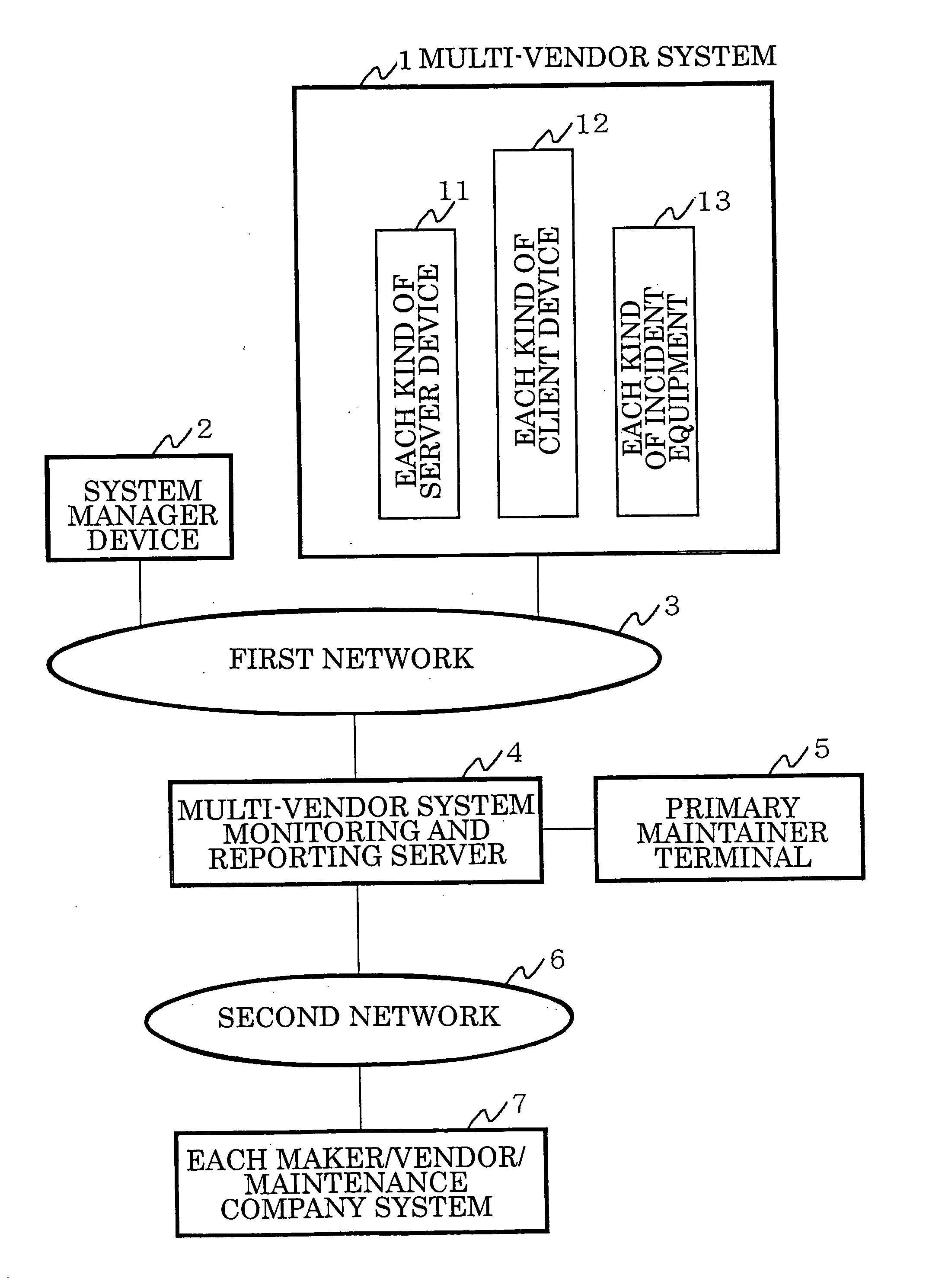
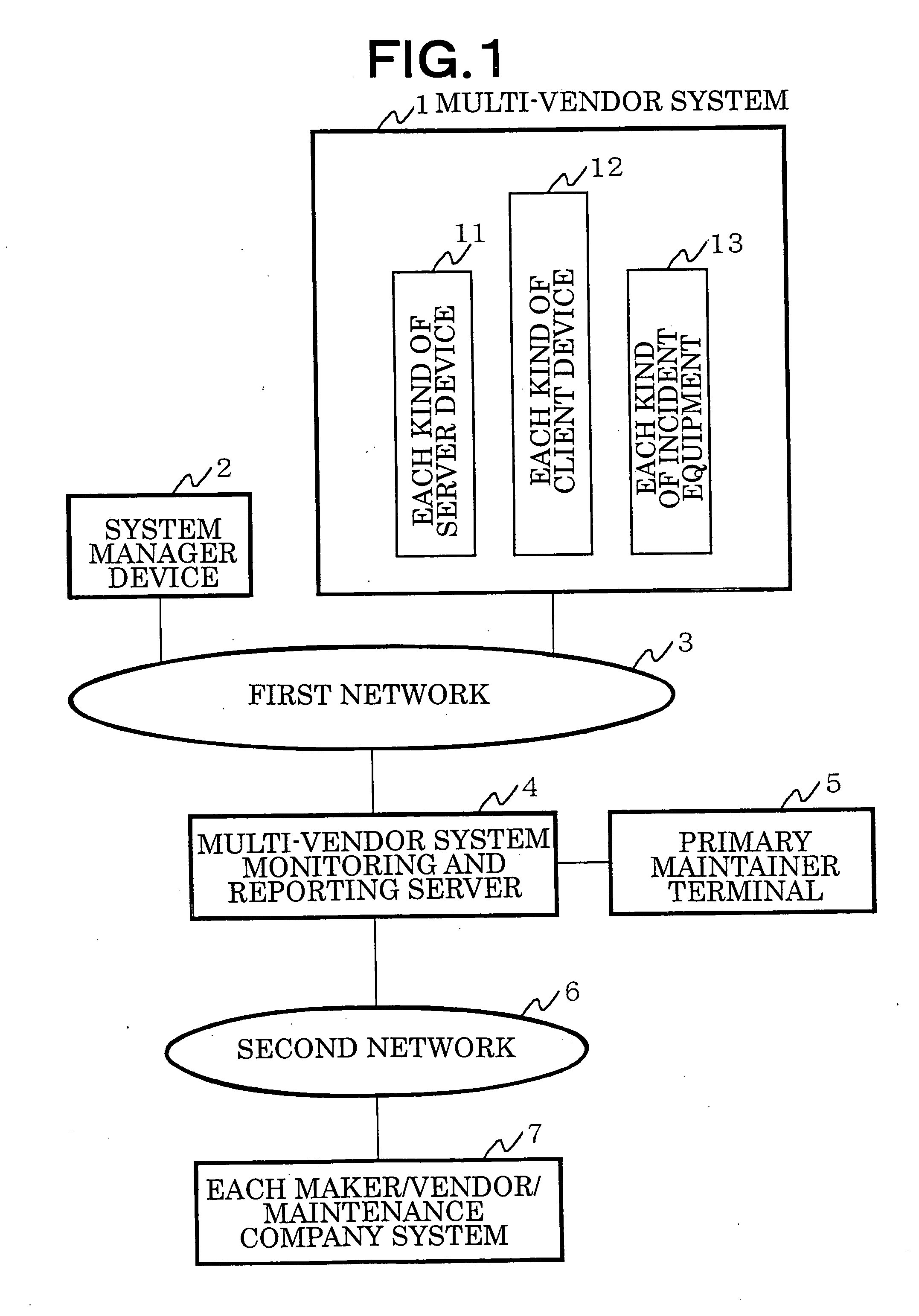
[0087] First, the concept of the maintenance service system according to the present invention will be described with reference to FIG. 1. FIG. 1 is a diagram showing the concept of the maintenance service system according to the present invention.

[0088] Referring to FIG. 1, the maintenance service system according to the present invention is equipped with a multi-vendor system 1, a system manager device 2, a first network 3, a multi-vendor system monitoring and reporting server 4, a primary maintainer terminal 5, a second network 6, each maker / vendor / maintenance company system 7.

[0089] The multi-vendor system 1 contains various types of server devices 11, var...


PUM


Abstract

A multi-vendor system monitoring and reporting server is connected to a multi-vendor system. The multi-vendor system monitoring and reporting server receives and recognizes plural different trouble reporting interfaces transmitted from respective devices constituting the multi-vendor system, and automatically reports occurrence of a trouble to a system manager device, a primary maintainer terminal and each maker / vendor / maintenance company system. The primary maintainer terminal creates trouble progress information, trouble completion information, etc. and reports the trouble information from the multi-vendor system monitoring and reporting server. The primary maintainer serves as a primary maintainer to collectively perform trouble information collection, trouble dealing work and trouble management, and performs system operation, presentation of management information and discussions and adjustments of the process management among respective vendors.

Description

BACKGROUND OF THE INVENTION [0001] 1. Field of the Invention [0002] The present invention relates to maintenance service system, its method and program and particularly, to maintenance service system, method and program in a multi-vendor system. [0003] 2. Description of the Related Art [0004] According to a conventional maintenance service system, information on a trouble status of a host system is transmitted from a trouble monitoring program in the host system or a trouble monitoring device in the host system through a communication line, and the trouble status thus transmitted is monitored at a maintenance service center (see, for example, JP-A-H11-296480). [0005] There is also known another maintenance service system in which a trouble is sensed on the basis of management information of each device connected to LAN and reported to a maintenance service center through a communication line, the trouble is subjected to diagnosis analysis at the maintenance service center and a main...

Claims


Application Information

Patent Timeline
IPC IPC(8): G06F11/32G06F11/30G06F13/00G06F17/00H04L12/24
CPCG06Q30/06
Inventor KOJIMA, KENJI
Owner NEC FIELDING
Learn More