Connecting rod with lubricant tube

a technology of connecting rod and lubricant tube, which is applied in the direction of connecting rod bearings, machines/engines, mechanical equipment, etc., can solve the problems of engine quality lacking, objection to piston noise being a source of customer complaints, and increasing piston noise complaints, so as to achieve the effect of less oil pump demand and adaptability to existing connecting rod designs

Inactive Publication Date: 2005-04-14
GM GLOBAL TECH OPERATIONS LLC
View PDF9 Cites 23 Cited by
  • Summary
  • Abstract
  • Description
  • Claims
  • Application Information

AI Technical Summary

Benefits of technology

[0008] The invention provides a connecting rod having an external tube which is connected to a connecting rod body for carrying lubricant from the crank arm bore end to the pin bore end of the connecting rod body for well targeted lubrication. This design is much less affected by crankcase windage than rod or block squirters, and is readily adaptable to existing connecting ro...

Problems solved by technology

In recent years, piston noise complaints have been on the rise.
Objection to piston noise continues to be a source of customer complaints.
Even though normal piston noise is not indicative of eminent mechanical failure, customers may deem it as unacceptable and the engine as lacking quality.
Modern piston noise can be attributed to lateral instability of the piston assembly and lack of sufficient lubrication within the critical interfaces of the piston-to-bore and wrist pin joints.
Severe packaging constraints and ever increasing power demands have led to very short piston designs with rotund skirt profiles.
Furthermore, a challenging high temperature environment now exists for the piston and pin, which requires some means for supplemental cooling.
However, relatively dry cylinder bores and pin joints have resulted for a number of reasons.
Unfortunately, these necessary refinements exacerbate the dry scenario for the rec...

Method used


Image

  • Connecting rod with lubricant tube
  • Connecting rod with lubricant tube
  • Connecting rod with lubricant tube

Examples


Embodiment Construction

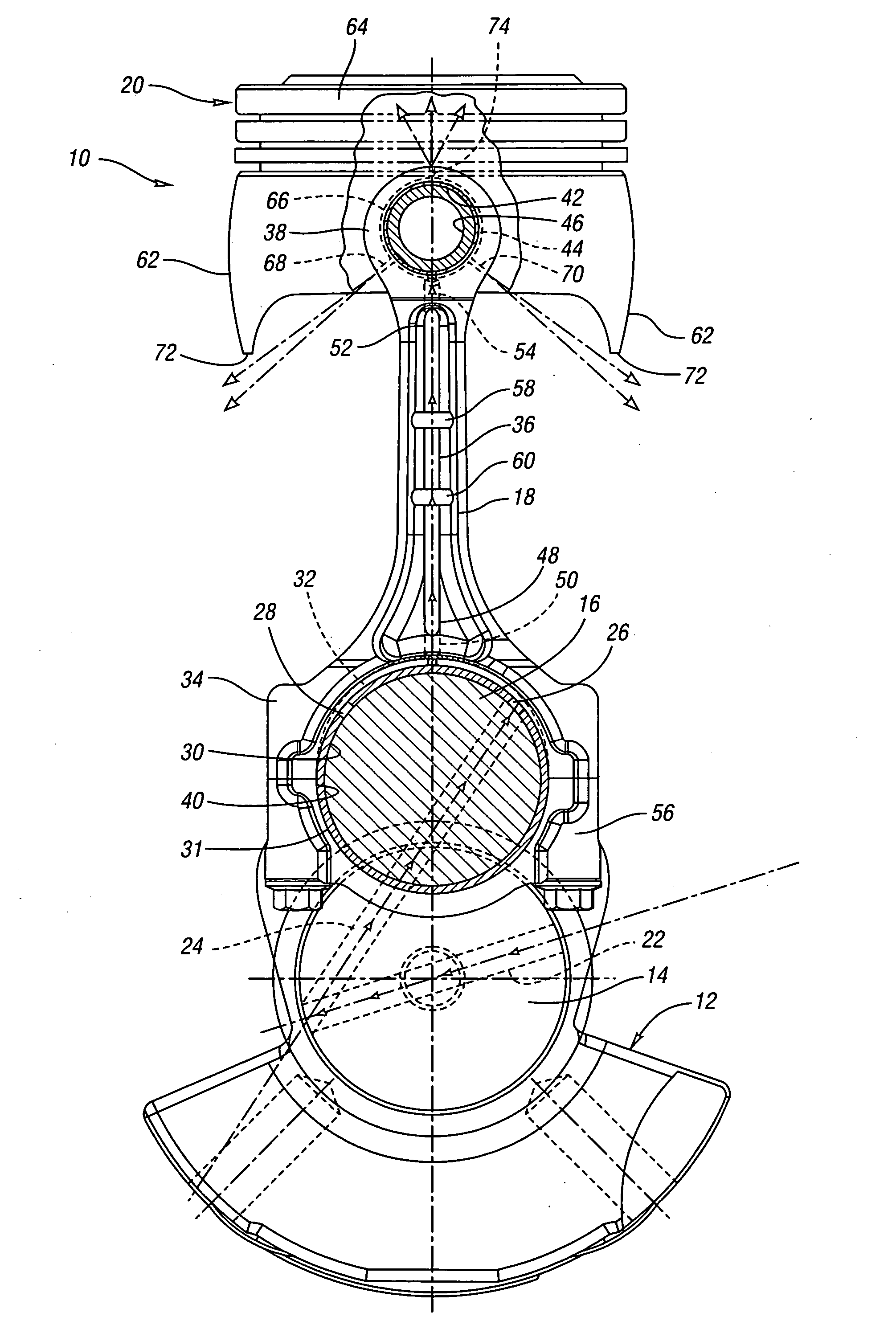
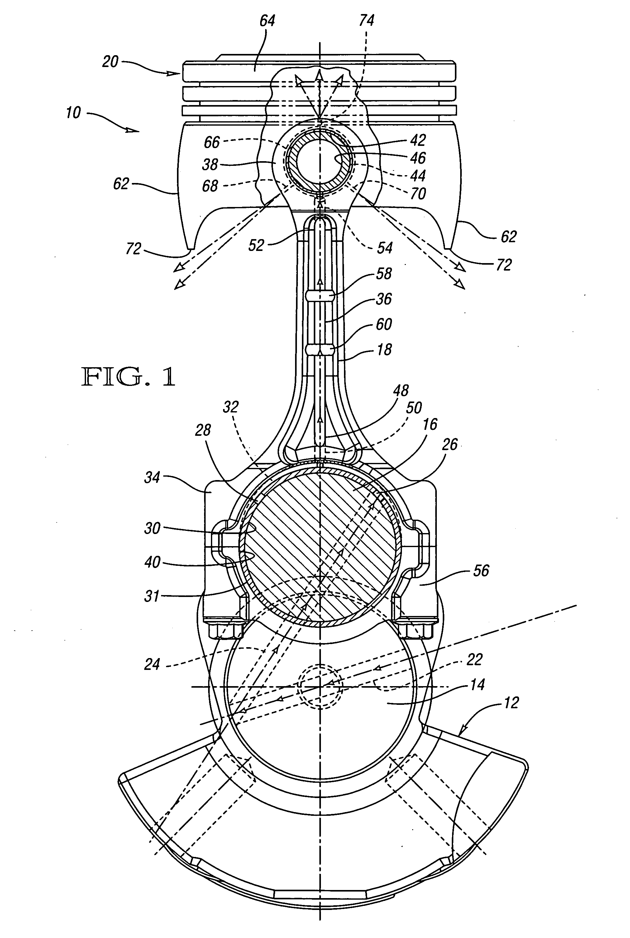
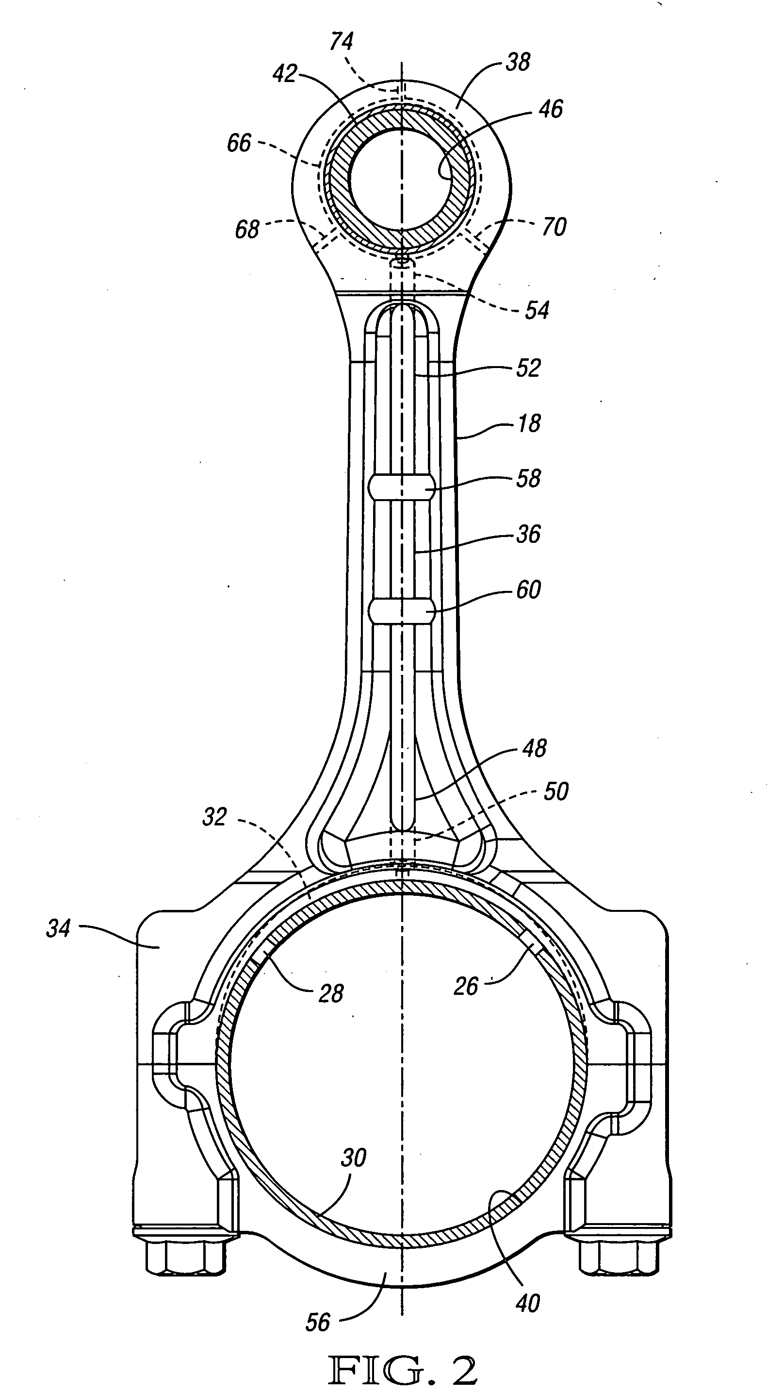
[0022] Referring to FIG. 1, a portion of an engine 10 is shown in accordance with the present invention illustrating a crank arm 12 on a crankshaft 14, which actuates a rod journal 16. Movement of the rod journal 16 actuates the connecting rod 18, which translates the piston 20 within a cylinder of the engine.

[0023] For lubrication, oil from the upper main bearing groove enters the main journal channel 22, and passes through the main journal of the crankshaft 14, through channel 24 within the crank arm 12, and into the rod journal 16. From channel 24, the oil passes through the openings 26, 28 in the upper rod bearing 30, and into the crescent shaped annulus 32 formed in the upper crank bore end 34 of the connecting rod 18. The crescent shaped annulus 32 is preferably machined to about 3 mm in width and about 1.5 mm at its deepest point.

[0024] A tube 36 is connected to the connecting rod 18 for carrying the oil from the annulus 32 of the crank bore end 34 to the pin bore end 38 of...


PUM


Abstract

A connecting rod includes a connecting rod body having a crank arm bore formed in a first end and a pin bore formed in a second end. A tube is connected to the body for carrying lubricant from the first end to the second end.

Description

TECHNICAL FIELD [0001] The present invention relates to a connecting rod having a tube positioned for carrying lubricant from one end of the connecting rod to another. BACKGROUND OF THE INVENTION [0002] In recent years, piston noise complaints have been on the rise. Piston noise includes “piston slap” and wrist pin knock or rattle. These noises are most frequently generated upon cold starting of the engine, but can also be manifest on hot restarts. Objection to piston noise continues to be a source of customer complaints. Even though normal piston noise is not indicative of eminent mechanical failure, customers may deem it as unacceptable and the engine as lacking quality. [0003] Modern piston noise can be attributed to lateral instability of the piston assembly and lack of sufficient lubrication within the critical interfaces of the piston-to-bore and wrist pin joints. Severe packaging constraints and ever increasing power demands have led to very short piston designs with rotund s...

Claims


Application Information

Patent Timeline
IPC IPC(8): F01M1/06F16C7/02
CPCF01M1/06F01M2001/062Y10T74/2162F16C7/023F01M2001/066F16C9/04F16C33/1045F16C2360/22
Inventor BEARDMORE, JOHN M.
Owner GM GLOBAL TECH OPERATIONS LLC
Why Eureka
Try Eureka