Heat spreader for plasma display panel

a plasma display panel and heat spreader technology, which is applied in the direction of identification means, electrical apparatus casings/cabinets/drawers, instruments, etc., can solve the problems of accelerating the thermal deterioration of affected discharge cells, prone to cracks and breakage of conventional plasma display panels, and difficult heat conduction in parallel directions to the panel fa

Active Publication Date: 2005-04-14
NEOGRAF SOLUTIONS LLC
View PDF11 Cites 24 Cited by
  • Summary
  • Abstract
  • Description
  • Claims
  • Application Information

AI Technical Summary

Benefits of technology

Yet another object of the present invention is to provide a method for applying a heat spreader material to a heat source such as a plasma display panel in a high volume manufacturing process where the application of the heat spreader does not create a bottleneck in the manufacturing process.
Another object of the present invention is to provide a heat spreader material which can be applied to a heat source or collection of heat sources such as a plasma display panel and adhere with good thermal contact between the heat spreader and the plasma display panel without the requirement of high pressure application of the spreader to achieve the desired thermal contact.
Still another object of the present invention is to provide a heat spreader material which can be applied to a heat source or collection of heat sources such as a plasma display panel and adhere to the source without falling off during the assembly process.

Problems solved by technology

The heat generated in the discharge cells is transferred to the glass forming the base plates, but heat conduction in directions parallel to the panel face is difficult because of the properties of the glass base plate material.
Because of this, the panel face temperature of the plasma display panel rises locally in the areas where an image is being generated, accelerating thermal deterioration of affected discharge cells, unless some heat sinking measures are taken.
Further, since the temperature difference between activated and nonactivated discharge cells can be high, and, in fact, the temperature difference between discharge cells generating white light and those generating darker colors also can be high, a stress is applied to the panel unit, causing the conventional plasma display panel to be prone to cracks and breakage.
Thus, those cells having large voltages for activation become more susceptible to thermal deterioration and tend to exacerbate the breakage problem of the panel unit of the plasma display panel.
One drawback to the use of graphite sheets as heat spreaders for plasma display panels lies in the plasma display panel manufacturing process.
More specifically, plasma display panels are produced in very high volumes, and the process for applying a graphite heat spreader to the plasma display panel need be such that a bottleneck in the manufacturing process is not created.
Graphite sheet has a relatively low cohesive strength and removing the release liner without delaminating the graphite is a significant challenge.
The disadvantage of this approach is the need for an additional coating step, which increases manufacturing complexity and cost.
Furthermore, this method should allow for the achievement of very high speed of release of the release liner from the adhesive-coated graphite sheet, without delamination of the graphite, and yet not create an undesirably high reduction of the thermal properties of the graphite heat spreader.

Method used


Image

  • Heat spreader for plasma display panel
  • Heat spreader for plasma display panel
  • Heat spreader for plasma display panel

Examples


example 1

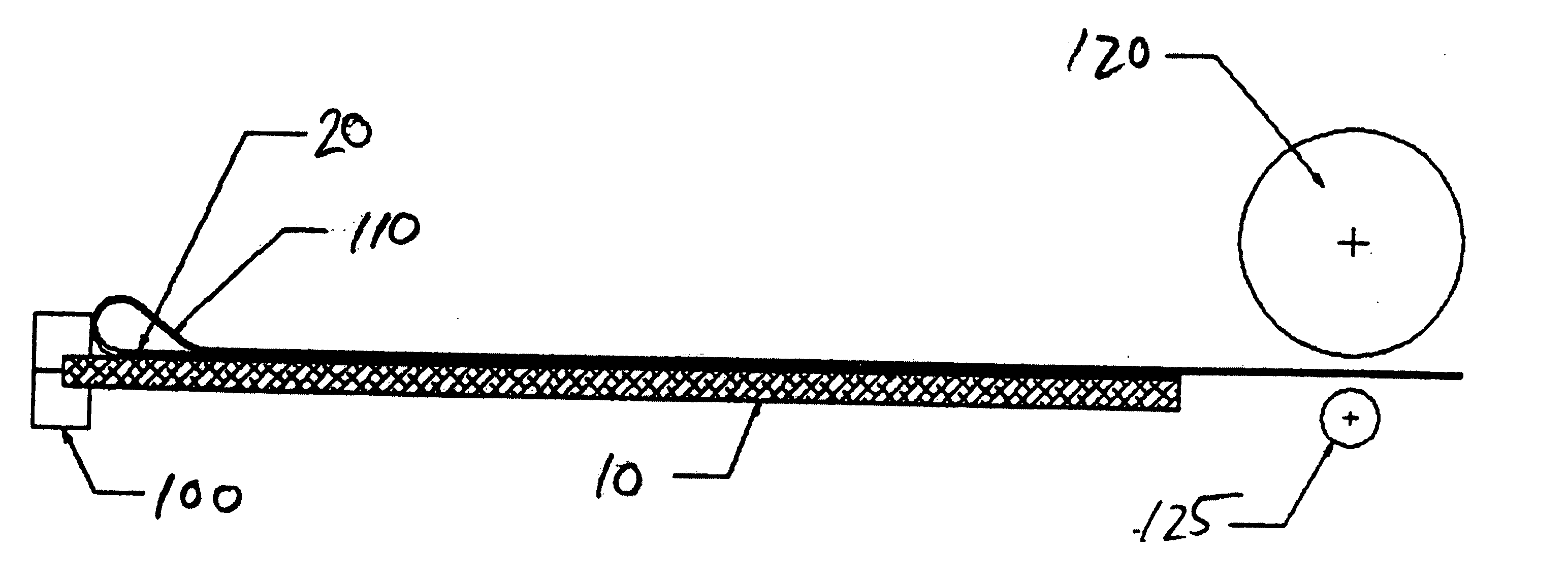
High speed release liner tests were performed using a ChemInstruments HSR-1000 high speed release tester. The test conditions were such that the drive wheel speed was set at 400, 800 feet / minute, a release angle of 180 degrees, surface release speed of 40, 80 inches / second, a spreader release rate of 0.5, 0.25 seconds and a sample size of 2 inches by 8 inches.

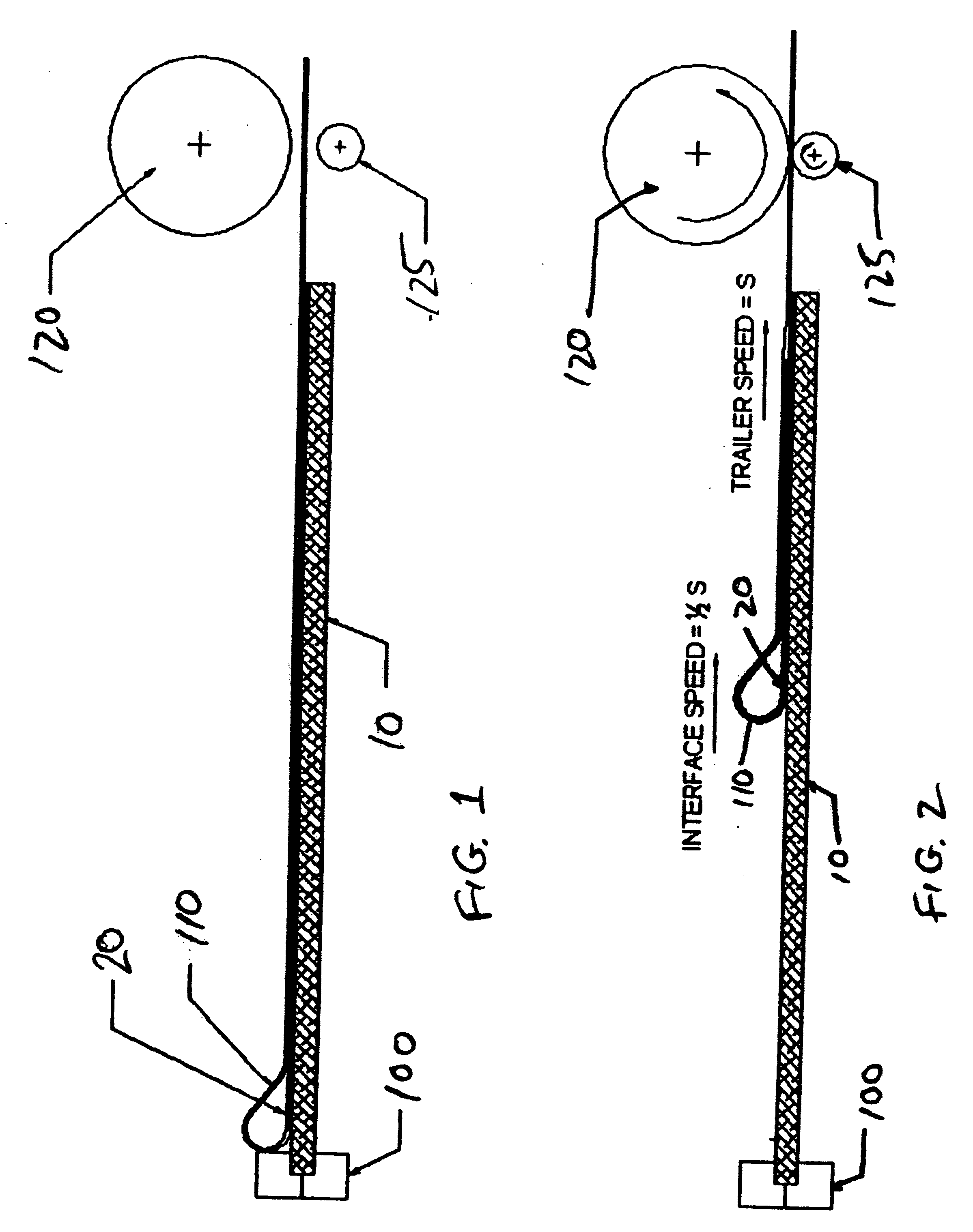
The diagram of the high speed release test is shown in FIG. 1. The release liner 20 is peeled back slightly from one end exposing of the sample exposing the graphite heat spreader 10 and the release liner 20. The exposed end of the graphite 10 is firmly held in place with a clamp 100 while a paper trailer 110 is attached to the free end of release liner 20. Paper trailer 110 is then double backed on itself and is fed between a drive wheel 120 and an idler wheel 125. The test involves driving the drive wheel 120 at a set speed and pressed against paper trailer 20, which is supported by idler wheel 125 illustrated in FIG. 2. T...

example 2

Lap shear adhesion tests were performed using Chem Instruments TT-1000 tensile tester. Test conditions were set such that crosshead speed is 0.5 inches / minute, lap shear area size is 1″ by 1″. eGraf specimen size was 1″ wide by 4″ long. Test substrate material glass and test substrate size 2″ wide by 4′ long. Specimens were die cut from each sample shear after affixing the sample to the glass substrate, a 1,000 gram weight was applied to the graphite / glass joint on the graphite side for 20 minutes prior to testing. No other forces were applied to the joint.

Samples were assembled in the tensile tester with the glass substrate located in the upper jaw and the sample located in the lower jaw. Tests were conducted at a crosshead speed of 0.5″ per minute. Maximum lap shear were obtained for each sample and are summarized in table II.

As shown in Table II, 100 samples of eGraf 755 graphite heat spreader coated with Aroset 3250 adhesive were tested, along with 10 samples of eGraf 755 h...

example 3

Probe tack tests were performed using a ChemInstruments PT-1000 Probe Tack Tester. Probe tack measures the initial “grab” of the adhesive on a substrate under no load conditions. Probe tack loads were obtained for samples of eGraf 755 graphite heat spreader coated with Aroset 3250 adhesive and Aroset 3300 adhesive, respectively and the results are summarized in Table III.

As shown in Table III, Probe Tack Tests were carried out on 26 samples coated with Aroset 3250 adhesive and 16 samples coated with Aroset 3300 adhesive. The Aroset 3250 samples came from 3 spreaders while the Aroset 3300 samples came from 2 spreaders. The average of the Probe tack loads for the Aroset 3250 adhesive coated samples was 23 grams while the average for the Aroset 3300 adhesive coated samples was 19.1 grams. The standard deviation for the Aroset 3250 coated samples was 10.5 grams while that for the Aroset 3300 adhesive coated samples was 9.0 grams, indicating that on average, there is a 17% reduction i...


PUM

PropertyMeasurementUnit
speedaaaaaaaaaa
release speedaaaaaaaaaa
thicknessaaaaaaaaaa

Abstract

The invention presented is a method for applying heat spreaders to a plurality of plasma display panels, including (a) providing a plurality of heat spreader composites, each of which comprises a heat spreader material having an adhesive thereon and a release material positioned such that the adhesive is sandwiched between the heat spreader material and the release material; (b) removing the release material from a plurality of the composites; and (c) applying at least one of the composites to each of the plurality of plasma display panels each such that the adhesive adheres the heat spreader material to the plasma display panel.

Description

TECHNICAL FIELD The present invention relates to a heat spreader useful for a plasma display panel for and a method of applying the inventive heat spreader to a plasma display panel. BACKGROUND OF THE ART A plasma display panel is a display apparatus which contains a plurality of discharge cells, and is constructed to display an image by applying a voltage across electrodes discharge cells thereby causing the desired discharge cell to emit light. A panel unit, which is the main part of the plasma display panel, is fabricated by bonding two glass base plates together in such a manner as to sandwich a plurality of discharge cells between them. In a plasma display panel, the discharge cells which are caused to emit light for image formation generate heat and each thus constitutes a |source of heat, which causes the temperature of the plasma display panel as a whole to rise. The heat generated in the discharge cells is transferred to the glass forming the base plates, but heat conduc...

Claims


Application Information

Patent Timeline
Patent Type & Authority Applications(United States)
IPC IPC(8): B32B9/00B32B9/04B32B33/00B32B43/00F28F7/02G06F1/20G09F9/00G09GH01J7/24H01J11/02H01J17/28H01J17/49H05K5/00H05K7/20
CPCB32B9/00B32B43/006H01J7/24Y10T428/14H01J2211/66H05K7/20963H01J9/20H01J11/20H01J2217/492B32B7/12B32B9/007
Inventor NORLEY, JULIANSMALC, MARTIN DAVIDCAPP, JOSEPH PAULCLOVESKO, TIMOTHY
Owner NEOGRAF SOLUTIONS LLC
Why Eureka
Try Eureka