Low-pressure dischage lamp and back light device using same

a low-pressure discharge and back light technology, applied in the direction of low-pressure discharge lamps, discharge tubes, luminescent screens, etc., can solve the problems of short lamp life, abnormal glow discharge transition, and decrease of emitted luminous flux

Inactive Publication Date: 2005-04-14
PANASONIC PHOTO & LIGHTING CO LTD +1
View PDF6 Cites 13 Cited by
  • Summary
  • Abstract
  • Description
  • Claims
  • Application Information

AI Technical Summary

Problems solved by technology

This results in a phenomenon in which a glow discharge transition from normal glow to abnormal glow is caused.
By the abnormal glow, the consumption of a rare gas sealed in a low-pressure discharge lamp is accelerated as a result of a rapid increase in the sputtering amount of an electrode material, thereby causing a problem of a short lamp life.
Furthermore, the use of a thin tube structure and a large current density, and a reduction in space for a low-pressure discharge lamp unit cause an atmospheric temperature during lighting of a low-pressure discharge lamp to be increased excessively to a temperature not lower than a temperature at which an optimum level of an emitted luminous flux is maintained, thereby also causing a problem of a decrease in an emitted luminous flux.

Method used


Image

  • Low-pressure dischage lamp and back light device using same
  • Low-pressure dischage lamp and back light device using same
  • Low-pressure dischage lamp and back light device using same

Examples


example 1

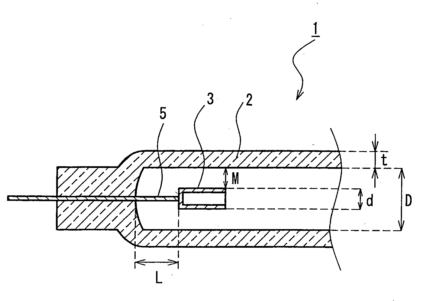
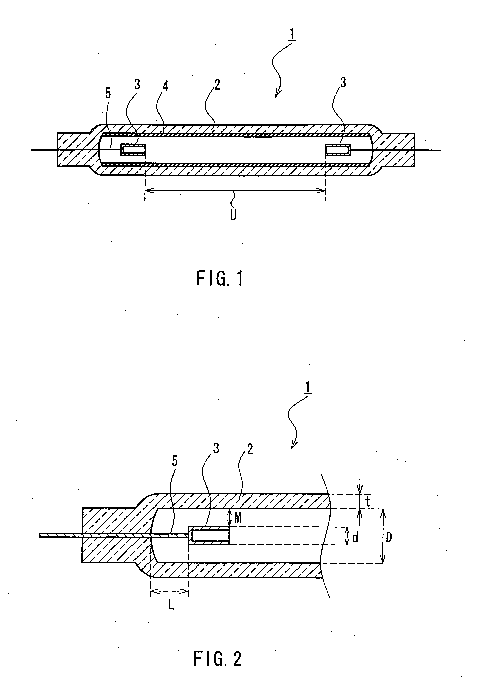
First, a low-pressure discharge lamp shown in FIG. 1 was manufactured in the following manner. That is, a three-wavelength-region emitting phosphor having a color temperature of 5,000 K was applied to the inner face of a glass tube in a thickness of about 20 μm. The glass tube was formed from borosilicate glass and had an outer diameter of 1.8 mm, an inner diameter of 1.4 mm, and a length of about 300 mm.

Next, a bottomed cylindrical electrode shown in FIG. 2 was formed. The cylindrical electrode was formed from niobium and had an outer diameter of 1.1 mm, an inner diameter of 0.9 mm, and a length of 1.5 mm. As an interior lead-in wire, a tungsten wire having an outer diameter of 0.6 mm was used. The interior lead-in wire was connected to the cylindrical electrode by resistance welding. In the glass tube, 1,500 μg of mercury and a neon-argon mixed gas of 95 vol % neon and 5 vol % argon were sealed at different sealing pressures, and thus sample lamps that vary in the sealing press...

example 2

Next, with respect only to Sample lamp group (a) described above, the respective composition ratios of argon and neon in the sealed gas were set so as to vary. In this manner, sample lamps that vary in the composition ratios of argon and neon were manufactured and grouped into Sample lamp group (c). With respect to each of the sample lamps, a lighting test was performed so as to determine a cathode glow discharge density (J). The result showed that by satisfying the above-mentioned expression, which is shown below, the following were achieved. That is, rare gas consumption attributable to increased sputtering of an electrode was not caused, normal glow discharge could be maintained, and degradation of a luminous flux hardly occurred. Thus, a long life (50,000 hours) could be secured, and excellent starting characteristics also could be attained up to the end of the life time.

Expression: α≦J=I / (S·P2)≦1.5α

[α=(90.5A+3.4N)×10−3]

In the above-mentioned expression, 1.5α that represents ...

example 3

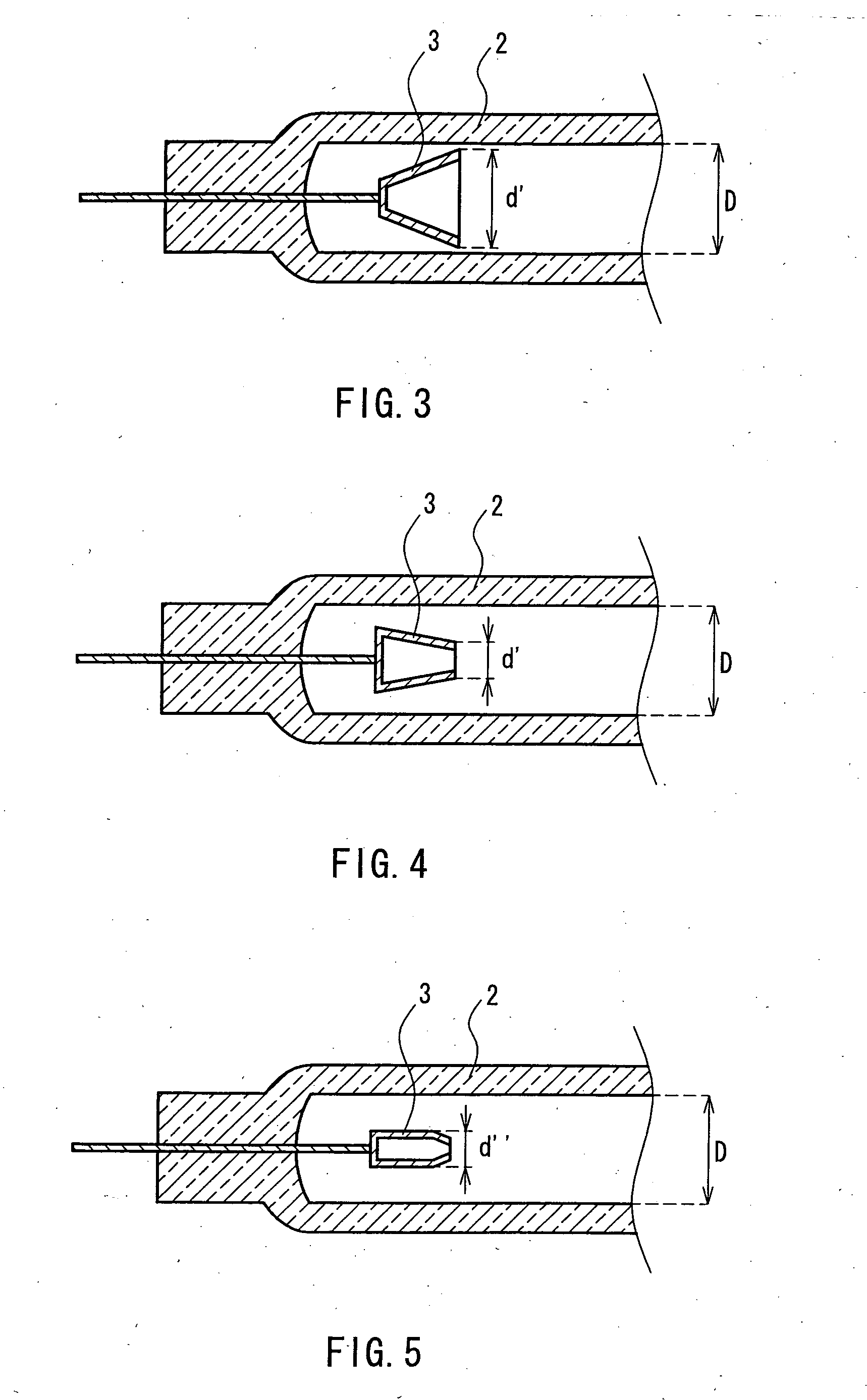
Next, a cap-like electrode 6 shown in FIG. 7, which had a shape different from that shown in FIG. 2 as the shape used in the case of Sample lamp group (a) described above, was fitted on an electrode bar 7. Using the cap-like electrode 6 and the electrode bar 7, sample lamps for Sample lamp group (d) were manufactured in accordance with various conditions. With respect to each of the sample lamps, a cathode glow discharge density (J) was determined. In this case, Sample lamp group (d) had the same configuration as that of Sample lamp group (c) except for the shape of the electrode. The cap-like electrode 6 had an outer diameter r1 of 0.9 mm and a length l of 2.5 mm. The electrode bar 7 had a diameter r2 of 0.6 mm.

As a result of the above-mentioned determination, with regard to the cathode glow discharge density (J) obtained in the case of Sample lamp group (d), as in the test results obtained in the case of Sample lamp group (c), in each of the sample lamps of a low-pressure disch...


PUM


Abstract

A low-pressure discharge lamp (1) is provided that includes a glass tube (2) having an inner diameter in a range of 1 to 5 mm and a pair of electrodes (3) disposed at end portions in the glass tube (2). The pair of electrodes (3) contain at least one transition metal selected from transition metals of Groups IV to VI. Mercury and a rare gas containing argon and neon are sealed in an inner portion of the glass tube (2). A relationship between a cathode glow discharge density J and a composition index α of the sealed rare gas of the low-pressure discharge lamp (1) satisfies the following expression α≦J=I / (S·P2)≦1.5α(where S represents an effective discharge surface area (mm2) of an electrode, I represents a RMS lamp current (mA), P represents a pressure (kPa) of a sealed rare gas, and α represents a composition index of a sealed rare gas that is a constant expressed by α=(90.5A+3.4N)×10−3 when a total of a composition ratio A of argon and a composition ratio N of neon is expressed by A+N=1). Thus, sputtering of a small-sized electrode is suppressed thereby to suppress consumption of a rare gas sealed in a lamp so as to increase a life time, and a decrease of an emitted luminous flux is prevented.

Description

TECHNICAL FIELD The present invention relates to a low-pressure discharge lamp that is used in a back light for various types of liquid crystal displays and the like. Specifically, this invention relates to a cold cathode fluorescent lamp of a small tube diameter including a cylindrical electrode with a hollow structure that is suitable for long-life use, and a back light device using the same. BACKGROUND ART Conventionally, with the diversification of liquid crystal displays, various studies have been carried out on a low-pressure discharge lamp for a back light device in order to achieve a thin tube structure, a high luminance, a long life and the like. As one of the methods for achieving these, a method is known in which an electrode made from a material having a low work function such as nickel is formed in any of various shapes including the shapes of a bar, a cylinder, a bottomed cylinder, a cap and the like so as be decreased in size as much as possible. This method suppres...

Claims


Application Information

Patent Timeline
Patent Type & Authority Applications(United States)
IPC IPC(8): F21S2/00F21Y103/00H01J61/067H01J61/16H01J61/72
CPCH01J61/72H01J61/067
Inventor YAMASHITA, HIROFUMIYAMAZAKI, HARUOTERADA, TOSHIHIROKIHARA, SHINJI
Owner PANASONIC PHOTO & LIGHTING CO LTD
Why Eureka
Try Eureka