Dual phase pulse modulation encoder circuit

a technology of encoder circuit and encoder, which is applied in the field of modulation of digital data, can solve the problems of power consumption requirements, potential signal propagation error recovery and the recovery of original information

Active Publication Date: 2005-04-14
ATMEL CORP
View PDF41 Cites 28 Cited by
  • Summary
  • Abstract
  • Description
  • Claims
  • Application Information

AI Technical Summary

Problems solved by technology

Some factors to consider in choosing a particular form of modulation include bandwidth, power consumption requirements, and the potential for signal propagation errors and recovery of the original information.

Method used


Image

  • Dual phase pulse modulation encoder circuit
  • Dual phase pulse modulation encoder circuit
  • Dual phase pulse modulation encoder circuit

Examples


Embodiment Construction

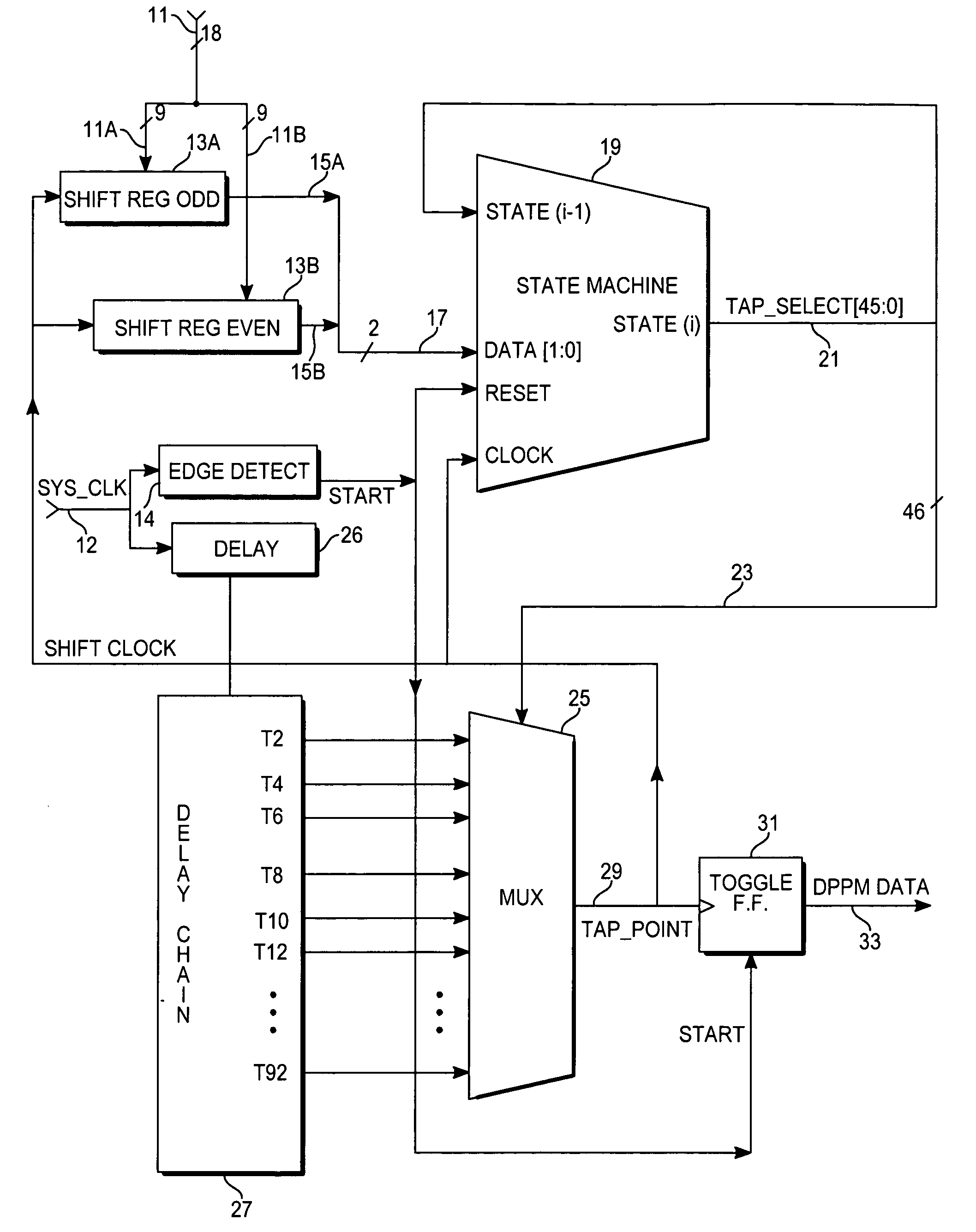
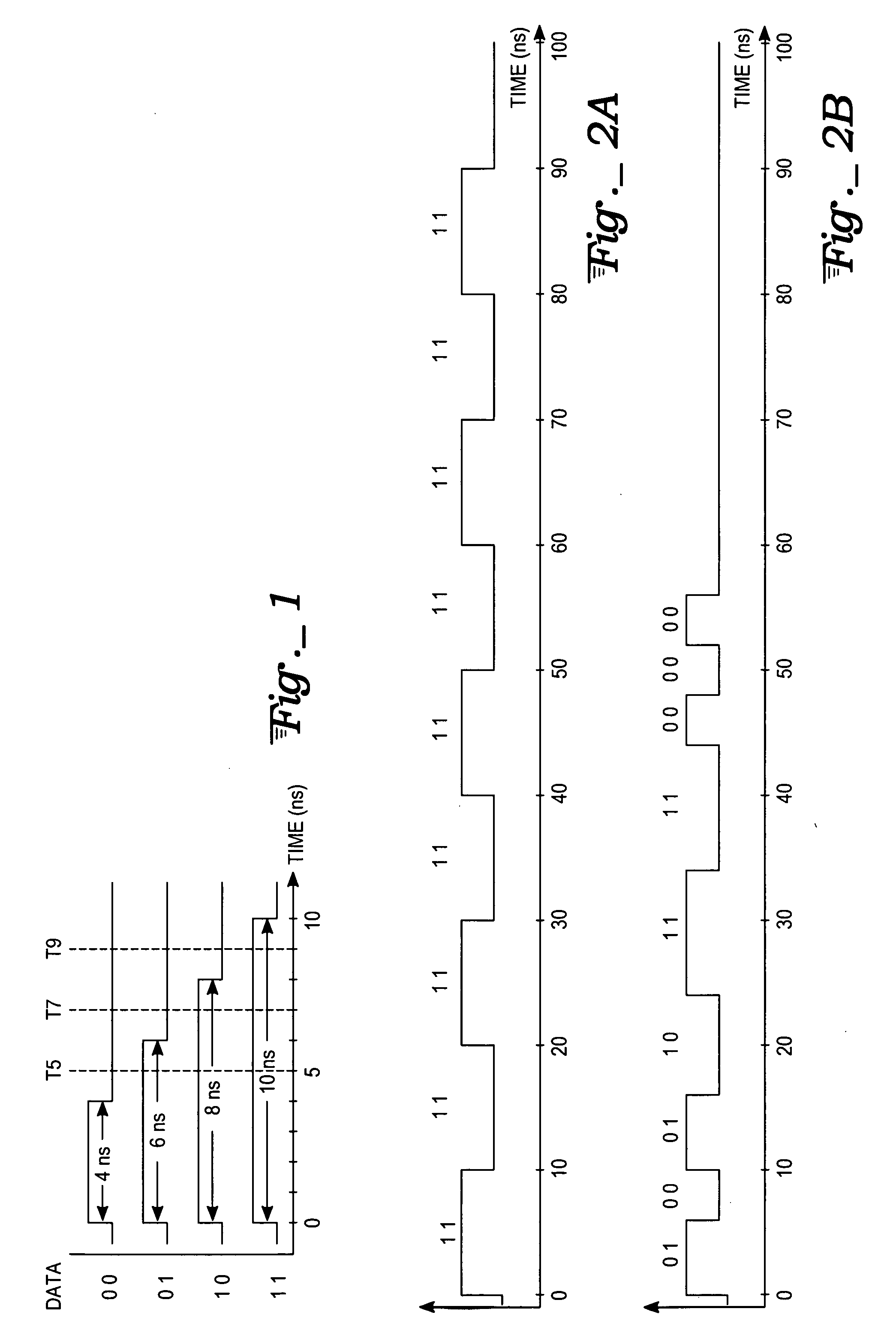
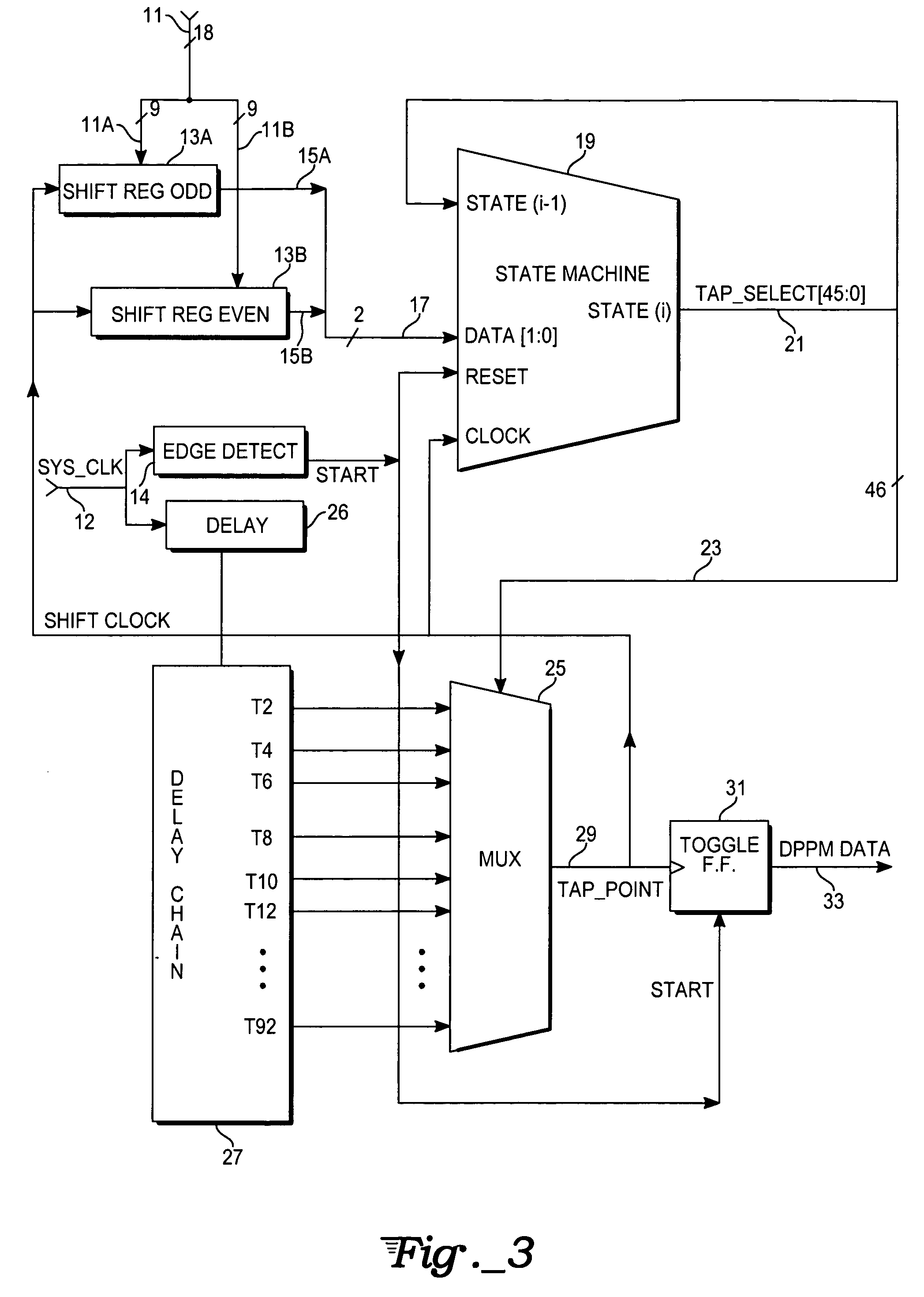
The present invention is an encoder circuit (an embodiment of which is shown in FIG. 3) that carries out dual phase pulse modulation (DPPM). DPPM is a method of encoding data, resident in digital circuitry in the form of binary circuit states (ones and zeros), as a string of alternating high and low signal pulses whose respective durations or widths represent 2 (or more) bits of data per pulse. An exemplary embodiment shown in FIG. 1 uses 2 bits for encoding. The pairs of bits are encoded using a set of distinct pulse widths representing each possible dibit symbol value, such as: 00=4 ns pulse 01=6 ns pulse 10=8 ns pulse 11=10 ns pulse

The choice of 4, 6, 8, and 10 ns pulse widths is arbitrary and could just as well have been 4, 5, 6, and 7 ns or some other pulse widths, provided the decoding circuitry at the receiving end of a DPPM signal transmission can correctly distinguish the different pulse widths from each other. The decoding circuitry (as well as process variation, no...


PUM


Abstract

An dual phase pulse modulation (DPPM) encoder circuit converts data into a series of high and low signal pulses, each of whose time durations or pulse widths represents a group of M data bits, with the alternating high and low pulses representing successive groups. The encoder circuit may include a set of parallel-in, serial-out shift registers that subdivide received data words into the M-bit groups, a state machine that specified the pulse durations for each received group, e.g., by incrementing a state that indicates selected signal pulse transition times, a system clock delay chain with multiple taps, a multiplexer controlled by the state machine for successively selecting different taps, and a toggle flip-flop that is clocked by the multiplexer output.

Description

TECHNICAL FIELD The present invention relates to modulation of digital data for signal transmission and corresponding demodulation of received signals to recover digital data carried thereby, and relates especially to the particular type of modulation used to encode the data, such as pulse-duration (width) modulation (PDM or PWM), on / off keying, non-return-to-zero (NRZ) schemes, differential phase-shift keying (DPSK), multiple-frequency-shift keying (MFSK), and various forms of multi-bit / N-ary encoding. BACKGROUND ART Communication signals are typically classified according to modulation type. Each of the various forms of modulation has its own set of advantages and disadvantages relative to a specific application for which it will be used. Some factors to consider in choosing a particular form of modulation include bandwidth, power consumption requirements, and the potential for signal propagation errors and recovery of the original information. For digital data, whether a separa...

Claims


Application Information

Patent Timeline
Patent Type & Authority Applications(United States)
IPC IPC(8): H03MH03M5/06H03M5/08H04L27/04H04L27/12H04L27/20
CPCH03M5/08
Inventor COHEN, DANIEL S.FAGAN, JOHN L.BOSSARD, MARK A.
Owner ATMEL CORP
Why Eureka
Try Eureka