
Method and apparatus for LWD shear velocity measurement

a technology of shear velocity and method, which is applied in the direction of instruments, surveying, and well accessories, etc., can solve the problems of not being able to directly measure shear velocity from monopole logging, the technology has not yet been commercially applied in the oil and gas industry, and the refract is no longer refractibl

Inactive Publication Date: 2005-04-14
BAKER HUGHES INC
View PDF18 Cites 30 Cited by
  • Summary
  • Abstract
  • Description
  • Claims
  • Application Information

AI Technical Summary

Benefits of technology

The present invention is an apparatus and method of determining formation shear properties in a Logging while Drilling environment. In a preferred embodiment of the invention, a transmitter is operated at a frequency below a cut off frequency of a signal propagating through the drill collar so that the signal received at receiver is uncontaminated by the collar mode. The cutoff frequency is determined by the thickness of the drill collar. In a preferred embodiment of the invention, t

Problems solved by technology

A formation that has a shear wave velocity faster than the borehole fluid is called a ‘fast formation.’ However, in a formation where the shear velocity is slower than borehole fluid velocity, a ‘slow formation,’ the shear wave can no longer refract along the borehole wall, and the shear velocity cannot be directly measured from monopole logging.
Although the quadrupole shear wave has been extensively studied theoretically and a wireline quadrupole-logging tool was also proposed (Winbow et al., 1991 in U.S. Pat. No. 5,027,331), this technology has not yet been commercially applied to the oil and gas industry.
As discussed later in the application, the application of the dipole acoustic technology to LWD has a serious drawback caused by the presence of the drilling collar with BHA that occupies a large part of the borehole.
The drawback is that the formation dipole shear wave traveling along the borehole is severely contaminated by the dipole wave traveling in the collar.

Method used


Image

  • Method and apparatus for LWD shear velocity measurement
  • Method and apparatus for LWD shear velocity measurement
  • Method and apparatus for LWD shear velocity measurement

Examples


Embodiment Construction

The present invention is a method, system and apparatus for measuring shear wave formation velocities while a well is being drilled. To the extent that the following description is specific to a particular embodiment or a particular use of the invention, this is intended to be illustrative and is not to be construed as limiting the scope of the invention.

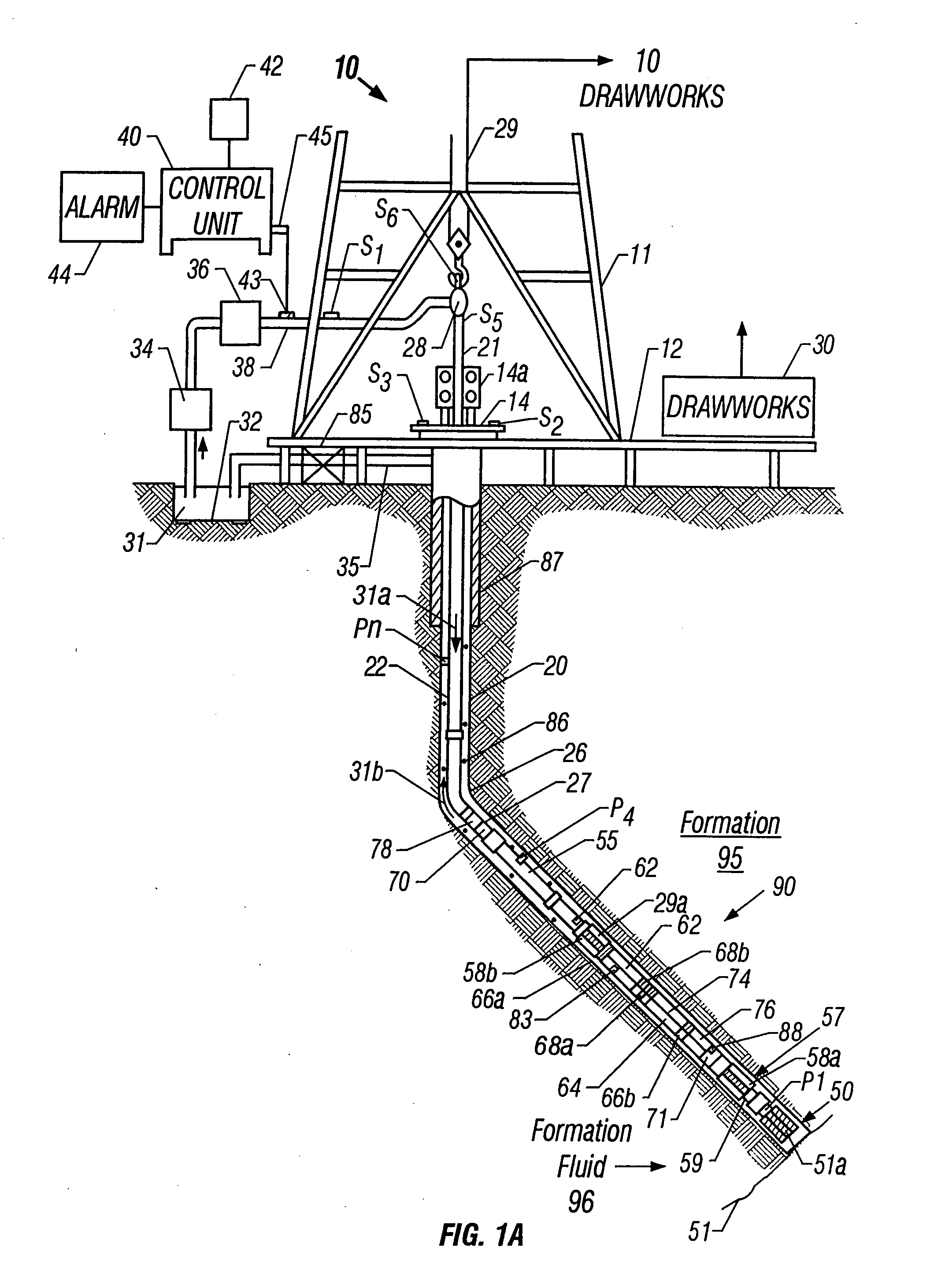
FIG. 1A shows a schematic diagram of a drilling system 10 having a bottom hole assembly (BHA) or drilling assembly 90 that includes sensors for downhole wellbore condition and location measurements. The BHA 90 is conveyed in a borehole 26. The drilling system 10 includes a conventional derrick 11 erected on a floor 12 which supports a rotary table 14 that is rotated by a prime mover such as an electric motor (not shown) at a desired rotational speed. The drill string 20 includes a tubing (drill pipe or coiled-tubing) 22 extending downward from the surface into the borehole 26. A drill bit 50, attached to the drill string 20 end, d...


PUM


Abstract

The logging tool of this invention includes a transmitter conveyed on a drilling collar for exciting a quadrupole signal in a borehole being drilled by a drill bit and a receiver for receiving the signal. The transmitter is operated at a frequency below the cut-off frequency of the quadrupole collar mode. The received signal consists primarily of the formation quadrupole mode which, at low frequencies, has a velocity that approaches the formation shear velocity. The transmitter, in one embodiment, consists of eight equal sectors of a piezoelectric cylinder mounted on the rim of the drilling collar. The value of the cut-off frequency is primarily dependent on the thickness of the drilling collar. Alternatively, the transmitter may be operated to produce both the collar mode and the formation mode and a processor may be used to filter out the collar mode.

Description

FIELD OF THE INVENTION This invention generally relates to a method and apparatus for measuring and processing a characteristic of subsurface earth formations penetrated by a borehole. More specifically this invention relates to a method and apparatus for measuring and processing an acoustic characteristic such as formation shear wave velocity of subsurface sonic waves after these waves traverse earth formations adjoining a borehole or passing through a portion of the subsurface. BACKGROUND OF THE INVENTION To obtain hydrocarbons such as oil and gas, wellbores (also referred to as the boreholes) are drilled by rotating a drill bit attached at the end of a drilling assembly generally referred to as the “bottom hole assembly” (BHA) or the “drilling assembly.” The wellbore path of such wells is carefully planned prior to drilling such wellbores utilizing seismic maps of the earth's subsurface and well data from previously drilled wellbores in the associated oil fields. Due to the ver...

Claims


Application Information

Patent Timeline
IPC IPC(8): E21B47/14E02D1/00G01VG01V1/00G01V1/40G01V1/44
CPCG01V1/44
Inventor TANG, XIAO MINGPATTERSON, DOUGLAS J.WANG, TSILILEGGETT, JAMES V. IIIDUBINKSY, VLADIMIR
Owner BAKER HUGHES INC
Features
  • Generate Ideas
  • Intellectual Property
  • Life Sciences
  • Materials
  • Tech Scout
  • Unparalleled Data Quality
  • Higher Quality Content
  • 60% Fewer Hallucinations
Learn More