Method of regulating reflectance of worm type optical recording medium and worm type optical recording medium

a technology of optical recording medium and reflectance, which is applied in the direction of optical recording/reproducing/erasing methods, instruments, flat record carrier containers, etc., can solve the problems of inability to write-once type optical media capable of high-speed recording with laser beams of wavelengths unable to achieve the synthesis of dyes, especially suitable for use with short wavelength laser beams that are blue or shorter than blue wavelengths, and low cost. , to achieve the effect o

Inactive Publication Date: 2005-04-14
TDK CORPARATION
View PDF6 Cites 42 Cited by
  • Summary
  • Abstract
  • Description
  • Claims
  • Application Information

AI Technical Summary

Benefits of technology

[0014] The present invention aims to resolve the conventional problems described above, with an object of providing a method for adjusting the reflectance of a write-once type optical recording medium, which utilizes an inorganic material, enables high-speed, high density write-once type optical recording using a laser beam with a wavelength that is either blue or an even shorter wavelength (200 to 450 nm), and in particular, is capable of easily and reliably maintaining compatibility with optical recording media of other types in relation to the reflectance, as well as a write-once type optical recording medium with a high level of production flexibility in terms of reflectance adjustment.

Problems solved by technology

However, no write-once type optical media capable of high-speed recording with laser beam of a wavelength shorter than blue wavelengths have yet been proposed.
However, when high speed recording is attempted, structures using organic dyes display inadequate recording sensitivity, and if the wavelength of the laser beam is shortened to improve the recording density.
Then currently, synthesis of a dye, especially suitable for use with a short wavelength laser beam that is blue or shorter than blue, is difficult.
Structures in which the recording layer is formed from an inorganic material have also been proposed (for example, Japanese Patent Publication No. 1992-838), although all of the current structures have numerous problems, including being unsuitable for high-speed recording, and displaying unsatisfactory storage reliability in a recorded state, and poor playback durability.
As a result, in those cases where, for example, information is recorded and played back by forming and detecting changes in reflectance, then if the reflectance varies depending on the type of optical recording medium or on the standard used, the drive system must be equipped with a broadband or multi-band structure capable of dealing with reflectance values from a plurality of standards, which increases the cost.
Furthermore, making the drive more compact and lighter weight also becomes difficult.
As a result, conventional systems have been unable to cope with the type of wide range of adjustments that are required to ensure compatibility between read only type reflectance and rewritable type reflectance, for example.

Method used


Image

  • Method of regulating reflectance of worm type optical recording medium and worm type optical recording medium
  • Method of regulating reflectance of worm type optical recording medium and worm type optical recording medium
  • Method of regulating reflectance of worm type optical recording medium and worm type optical recording medium

Examples


example 1

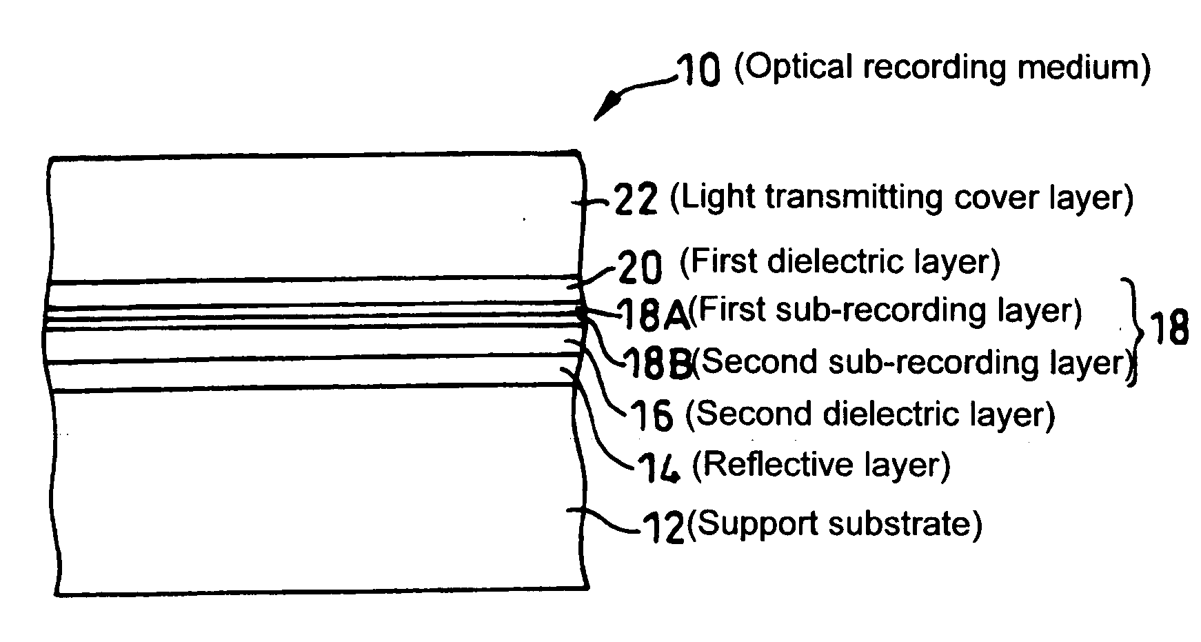
[0070] For the optical recording medium 10 described above, characteristics were evaluated for the relationship between the thickness of the recording layer 18 comprising a high reflectance metal as the primary component, and the reflectance.

[0071] The specific structure of each layer of the optical recording medium 10 for these evaluations is shown below.

[0072] Reflective layer 14: not formed

[0073] Dielectric layers 16, 20: ZnS+SiO2 (80:20 mol %)

[0074] First dielectric layer 20: 40 nm, second dielectric layer 16: 80 nm

[0075] First sub-recording layer 18A: AlCr (98:2 at %)

[0076] Second sub-recording layer 18B: Sb 10 nm

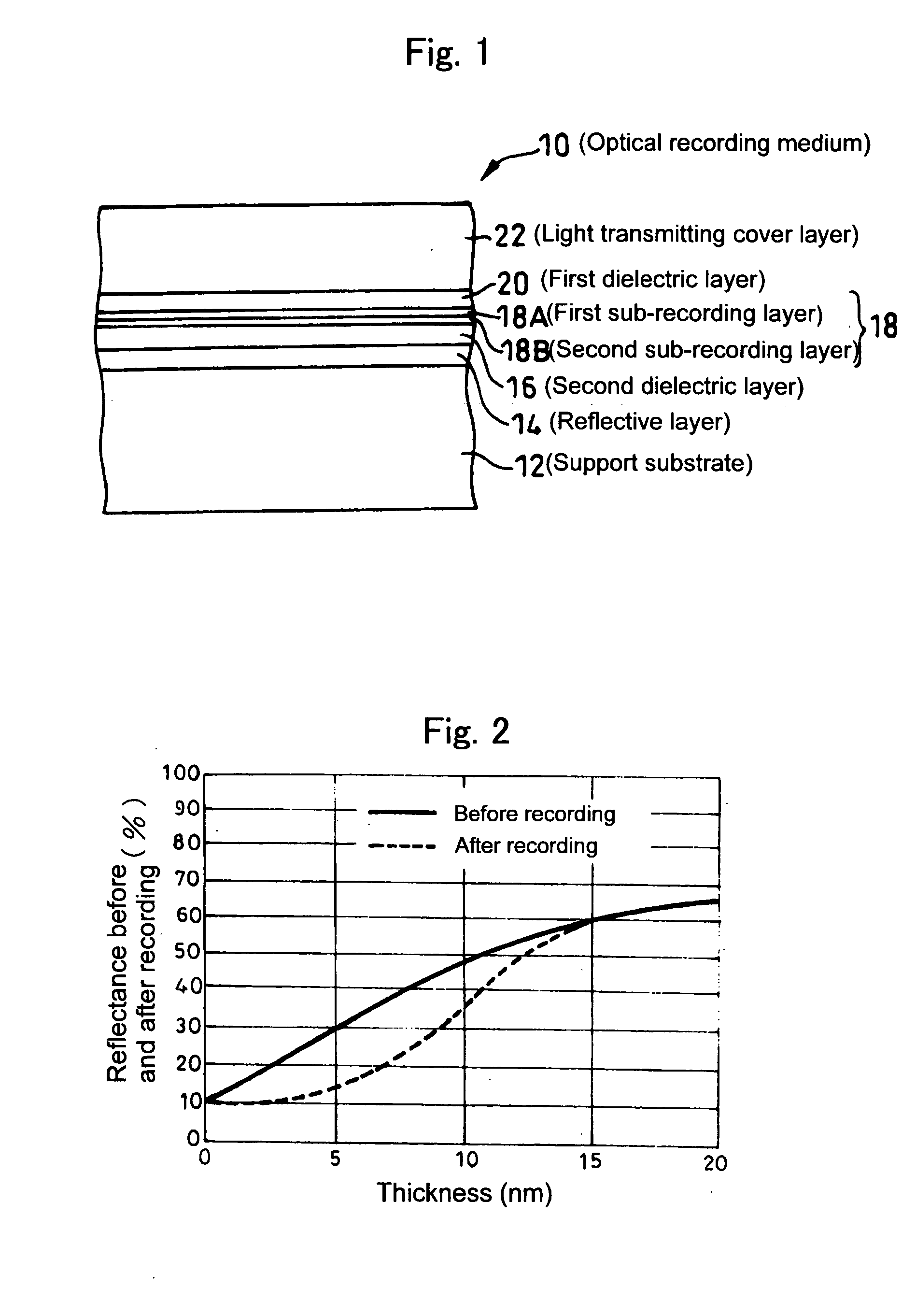
[0077] The thickness of the first sub-recording layer 18A was varied within a range from 0 to 20 nm.

[0078] Using an evaluation apparatus with a laser beam of wavelength 405 nm, recording was conducted under measurement conditions including a linear velocity of 5.3 m / s (35 Mbps) and a laser output of 10 mW, and the reflectance before and after formation of recor...

example 2

[0089] Next is a description of another example in which the reflectance is adjusted.

[0090] If the thickness of the recording layer of an optical recording medium 10 is set to no more than 20 nm, and a reflective layer 14 is formed, then the reflectance of the optical recording medium 10 is largely controlled by the reflection at the interface between the reflective layer 14 and the second dielectric layer 16.

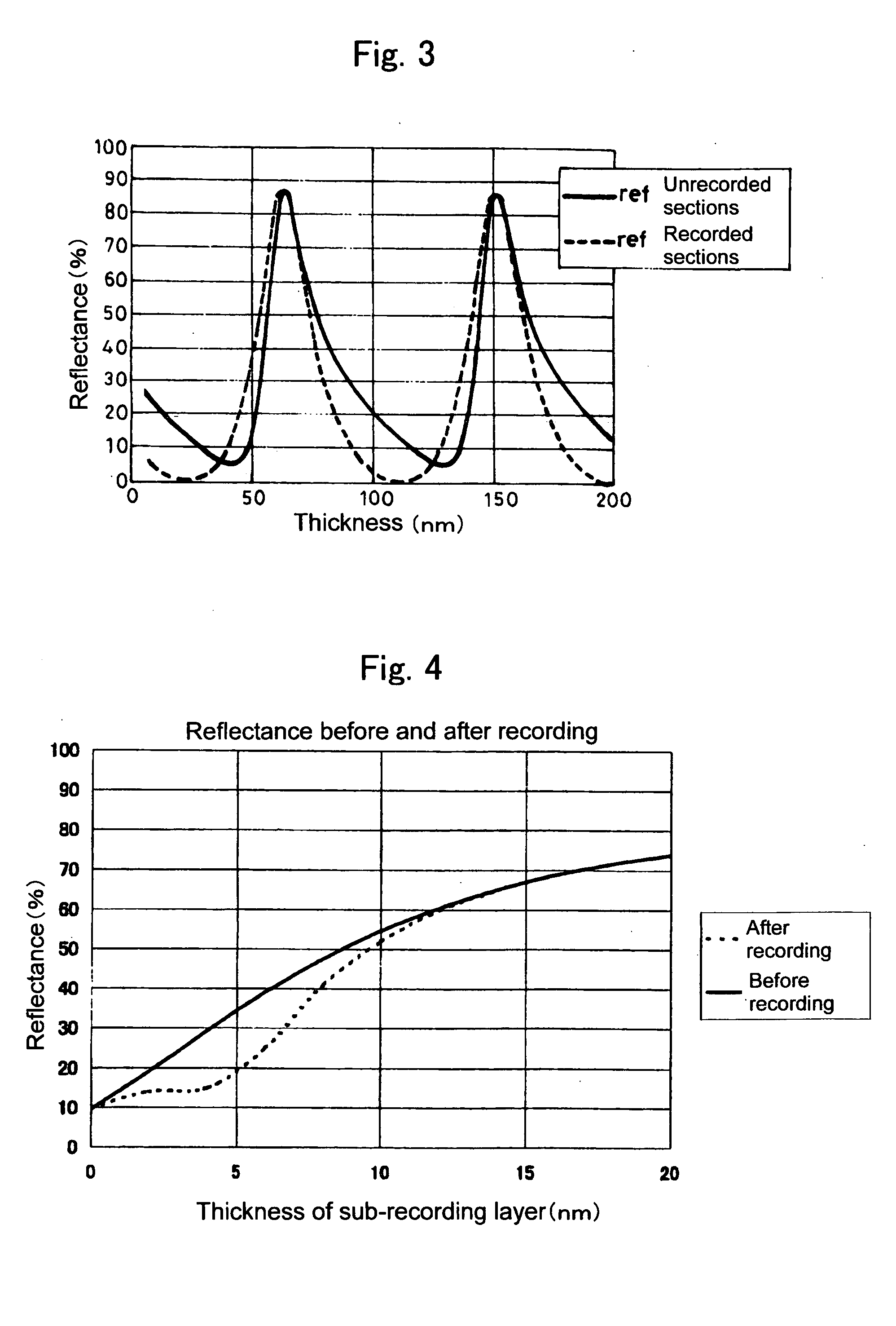
[0091] An evaluation was conducted of the reflectance characteristics when the thickness of the second dielectric layer 16 was varied. The conditions for the tests were as follows, and other conditions were the same as those described above for the example 1.

[0092] Reflective layer 14: silver alloy AgPdCu (98:1:1 at %) 100 nm

[0093] First dielectric layer 20: 55 nm (fixed)

[0094] Second dielectric layer 16: 5 to 200 nm

[0095] First sub-recording layer 18A: AlCr (98:2 at %) 4 nm

[0096] Second sub-recording layer 18B: Sb 6 nm

[0097] The results of the tests are shown in FIG. 3...

example 3

[0107] For the optical recording medium 10 described above, factors such as the material of the second sub-recording layer 18B were altered, and the characteristics were evaluated for the relationship between the thickness of the recording layer 18, comprising a high reflectance metal as the primary component, and the reflectance. The structure of each layer of the optical recording medium 10 for these evaluations is shown below. A reflective layer was not provided.

[0108] Dielectric layers: ZnS+SiO2 (80:20 mol %)

[0109] First dielectric 20: 60 nm,

[0110] Second dielectric 16: 60 nm

[0111] First sub-recording layer 18A: AlCr (98:2 at %)

[0112] Second sub-recording layer 18B: C 8 nm

[0113] The thickness of the first sub-recording layer 18A was varied within a range from 0 to 20 nm.

[0114] Using the evaluation apparatus with a wavelength of 405 nm, recording was conducted under measurement conditions including a linear velocity of 5.3 m / s and a laser output of 10 mW, and the reflectan...


PUM

PropertyMeasurementUnit
reflectanceaaaaaaaaaa

Abstract

The reflectance of an optical recording medium for which high speed recording using a laser beam with blue wavelength or a shorter wavelength than blue light is possible is adjusted to a predetermined value of no more than 60%. A recording layer 18 of a high-speed write-once type optical recording medium 10 is formed by laminating first and second sub-recording layers 18A, 18B, each of which contains one type of different metal as a primary component. When laser beam of a blue wavelength is irradiated onto the recording layer 18, the irradiation causes the primary component metals contained within each of the first and second sub-recording layers 18A, 18B to diffuse and mix, and this mixing forms a recording mark with an irreversibly changed reflectance. The recording layer 18 is sandwiched between first and second dielectric layers 20, 16, and by adjusting the material and the thickness of the recording layer 18 and the first and second dielectric layers 20, 16, the reflectance of the unrecorded sections can be adjusted to a value within a range from 5% to 60%.

Description

TECHNICAL FIELD [0001] The present invention relates to a method for adjusting the reflectance of a write-once type optical recording medium, particularly an optical recording medium for which high density recording using a laser beam with a shorter wavelength than blue light is possible, as well as a write-once type optical recording medium with a reflectance that has been adjusted using this adjustment method. BACKGROUND ART [0002] In recent years, optical recording media capable of high density, high-speed recording have been keenly sought, and optical recording media capable of undergoing recording and playback with laser beam at blue wavelengths are currently attracting attention as one specific solution. [0003] Among the optical recording media utilizing blue wavelength laser beam, playback only (ROM: read only memory) type optical recording media and rewritable (RW) type optical recording media have already been proposed. [0004] However, no write-once type optical media capab...

Claims


Application Information

Patent Timeline
Patent Type & Authority Applications(United States)
IPC IPC(8): G03G7/00G11B7/0045G11B7/005G11B7/24G11B7/24035G11B7/241G11B7/2433
CPCG03G7/0033G11B2007/25716G11B7/0052G11B7/24067G11B7/241G11B7/2433G11B7/2534G11B7/258G11B7/2585G11B7/259G11B7/2595G11B2007/24308G11B2007/2431G11B2007/24312G11B2007/24314G11B2007/25706G11B2007/2571G11B2007/25715G11B7/00455G11B7/26
Inventor MIZUSHIMA, TETSUROYOSHINARI, JIRO
Owner TDK CORPARATION
Why Eureka
Try Eureka